
The Core Problem: Why Arduino PNG Imports Fail
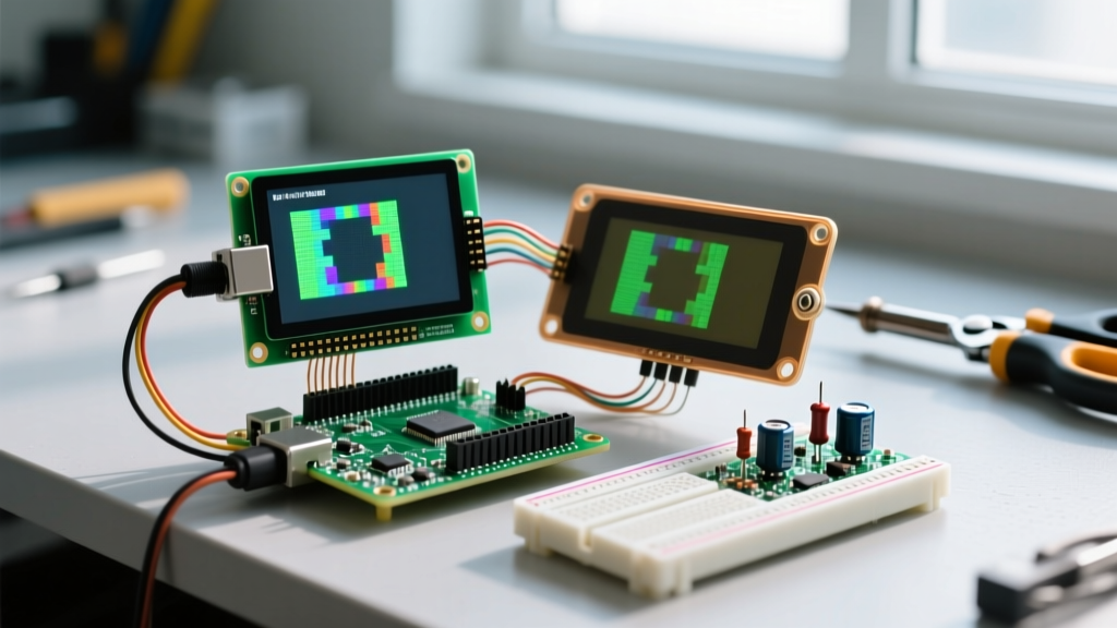
Converting and displaying an Arduino PNG file on a microcontroller-driven display is a rite of passage for embedded developers. Whether you are building a custom GUI on an ILI9341 TFT screen or rendering a logo on an SSD1306 OLED, the workflow usually involves converting a PNG image into a C-style hex array. However, this process is notoriously prone to failure. You upload your sketch, and instead of a crisp image, you are met with a scrambled mess of static, a completely white screen, or a compiler throwing a section '.text' will not fit in region 'iram1_0_seg' fatal error.
These Arduino PNG rendering errors almost always stem from three fundamental mismatches: memory architecture limits, color depth misconfigurations, or endianness conflicts within your graphics library. This diagnostic guide will dissect these failure modes and provide exact, actionable fixes for AVR and ESP32 architectures.
Diagnostic 1: Memory Overflows and PROGMEM Misallocation
The most common point of failure when importing an Arduino PNG array is exceeding the microcontroller's SRAM. A standard 320x240 pixel image at 16-bit color (RGB565) requires exactly 153,600 bytes (150 KB) of memory. If you declare this array as a standard variable, the compiler attempts to load it into SRAM at runtime.
- Arduino Uno R3 (ATmega328P): Features only 2 KB of SRAM. A 150 KB image will instantly cause a stack overflow, leading to a silent reboot loop or frozen execution.
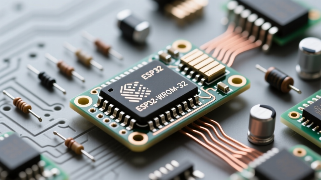
- ESP32-WROOM-32: Features roughly 520 KB of usable SRAM. While it can technically hold the image, consuming 30% of your RAM for a single static UI element will starve your Wi-Fi stack and FreeRTOS tasks, causing
Guru Meditation Error: Core 1 panic'ed (StoreProhibited).
The Fix: Enforcing Flash Storage via PROGMEM
To resolve SRAM exhaustion, the hex array must be stored in Flash memory (PROGMEM on AVR, or standard const in ESP32 XIP flash). According to the official Arduino Memory Guide, AVR boards require the explicit PROGMEM keyword, while ESP32 handles const arrays in flash automatically.
Incorrect (Causes SRAM Overflow):
const uint8_t myImage[] = { 0xFF, 0xD8, ... };Correct for AVR (Arduino Uno/Mega):
const uint8_t myImage[] PROGMEM = { 0xFF, 0xD8, ... };Correct for ESP32:
const uint16_t myImage[] = { 0xF81F, 0x07E0, ... }; // Stored in flash automaticallyDiagnostic 2: Color Depth and Conversion Tool Mismatches
If your code compiles and uploads successfully, but the display shows garbled lines, incorrect colors, or skewed geometry, the issue lies in the PNG-to-C conversion step. Tools like Image2Cpp or LCD Image Converter require precise configuration to match your target display's controller.
Color Depth Matrix: Matching PNG to Hardware
| Display Type | Common Controller | Required Color Depth | Bytes Per Pixel | Conversion Tool Setting |
|---|---|---|---|---|
| 0.96" OLED | SSD1306 | 1-bit Monochrome | 1/8 byte | 1-bit, Black/White threshold |
| 2.8" TFT | ILI9341 / ST7789 | 16-bit RGB565 | 2 bytes | 16-bit RGB565 (5-6-5) |
| E-Paper | SSD1681 | 2-bit to 4-bit Grayscale | Variable | 4-color palette mapping |
The Fix: Aligning Draw Functions with Array Formats
A frequent error occurs when developers generate a 16-bit RGB565 array but attempt to render it using a 1-bit function. The Adafruit GFX Library documentation explicitly separates these rendering pipelines. If you pass a 16-bit array to drawBitmap(), the library interprets every byte as 8 individual monochrome pixels, resulting in a stretched, chaotic barcode pattern.
- Use
drawBitmap(x, y, array, w, h, color)ONLY for 1-bit monochrome arrays (OLEDs). - Use
drawRGBBitmap(x, y, array, w, h)for 16-bit RGB565 arrays stored in RAM. - Use
drawRGBBitmap(x, y, array, w, h)with PROGMEM-specific overloads for Flash-stored 16-bit arrays.
Diagnostic 3: The Endianness Trap (Scrambled Colors)
If your Arduino PNG renders with the correct geometry but the colors are wildly incorrect (e.g., reds appear blue, blues appear red, or the image looks like a negative), you have encountered an endianness mismatch. This is highly prevalent when using ESP32 boards with the TFT_eSPI library.
Web-based conversion tools typically output 16-bit RGB565 hex values in Big-Endian format (e.g., 0xF800 for Red). However, the ARM Cortex-M and Xtensa architectures (which power the ESP32 and Arduino Due) process 16-bit integers in Little-Endian format. When the SPI bus shifts the bytes to the TFT controller, the high and low bytes are swapped, corrupting the color data.
The Fix: Byte Swapping in TFT_eSPI
Instead of manually rewriting your hex array or using a script to flip the bytes, the TFT_eSPI library repository provides a hardware-level toggle to handle this on the fly. Before calling your image push function, enable byte swapping:
tft.setSwapBytes(true);
tft.pushImage(x, y, width, height, myImageArray);
tft.setSwapBytes(false); // Revert if drawing other elements
Expert Tip: If you are reading PNG data dynamically from an SD card rather than a compiled C-array, the data is usually read byte-by-byte in Big-Endian order. In this specific SD-streaming scenario, you must set setSwapBytes(false) to prevent double-swapping the color channels.
Step-by-Step Diagnostic Workflow for Corrupted PNGs
When faced with an unrecognizable display output, follow this strict elimination sequence to isolate the Arduino PNG fault:
- Verify the Hex Header: Open your generated
.hfile. If the array is defined asuint8_tbut contains 16-bit color data, the conversion tool failed. Regenerate asuint16_t. - Check Dimension Variables: Ensure the
widthandheightvariables passed to your draw function exactly match the pixel dimensions of the original PNG. A mismatch of even 2 pixels will cause a diagonal 'tearing' effect across the screen. - Test with a Known-Good Array: Replace your custom PNG array with a standard library test image (like the Adafruit RGB test bitmap). If the test image renders correctly, your hardware and wiring are fine; the fault is strictly in your PNG conversion parameters.
- Inspect SPIFFS/LittleFS Offsets: If you are loading the PNG from ESP32 flash partitions, verify your
partitions.csvfile. An overlapping partition will cause the MCU to read executable code as image data, resulting in random noise.
Advanced Edge Cases: Bypassing Flash Limits on High-Res Displays
Modern maker projects frequently utilize 4.0-inch IPS displays (800x480 resolution). A single 800x480 RGB565 image requires 768 KB of storage. This exceeds the available application flash space on a standard ESP32-WROOM-32 (which typically reserves ~1.2MB for the sketch and the rest for OTA updates and SPIFFS).
Solution A: ESP32-WROVER PSRAM Utilization
If you upgrade to an ESP32-WROVER module equipped with 8MB of PSRAM, you can dynamically decode compressed PNG files at runtime. Using the PNGdec library, you can stream the decoded pixel lines directly into a PSRAM-allocated buffer, completely bypassing Flash storage limits and keeping your compiled binary size under 500 KB.
Solution B: SD Card Line-by-Line Streaming
For AVR boards or ESP32s without PSRAM, storing raw PNGs on a microSD card is mandatory. However, decoding a PNG natively on an ATmega2560 is impossible due to the lack of RAM for the zlib decompression buffer. The workaround is to pre-convert the PNG to a raw 16-bit binary file (.bin) on your PC, save it to the SD card, and use the SdFat library to read exactly 640 bytes (one 320-pixel row) at a time, pushing it to the TFT controller via DMA before fetching the next row.
Summary of Preventative Best Practices
To eliminate Arduino PNG rendering errors before they happen, standardize your asset pipeline. Always crop your PNGs to the exact pixel dimensions required to avoid off-by-one memory stride errors. Use uint16_t for all TFT assets and uint8_t for OLEDs. Finally, maintain a strict separation between your Flash-stored UI elements and your RAM-allocated dynamic buffers to ensure your microcontroller's watchdog timer never triggers a hard reset during graphical rendering.