
Transitioning an Arduino project from a cluttered breadboard to a robust, field-ready deployment is a critical milestone for any electronics engineer or maker. However, the physical housing—often casually referred to as an arduino box—is frequently an afterthought. In 2026, treating your project enclosure as a core component of your workflow optimization strategy can reduce assembly time by up to 40%, minimize debugging caused by loose connections, and ensure repeatable manufacturing for low-volume runs.
Whether you are building an environmental sensor node, a custom MIDI controller, or an industrial IoT gateway, the right Arduino box enclosure dictates your internal layout, thermal management, and I/O accessibility. This guide dives deep into material selection, internal architecture, and step-by-step assembly techniques to streamline your prototyping workflow.
The Prototyping Bottleneck: Why the Enclosure Matters
Most workflow delays in hardware prototyping occur during the 'boxing' phase. Makers often drill holes haphazardly into generic plastic cases, leading to misaligned USB ports, stripped screws, and internal short circuits. A standardized approach to your Arduino box eliminates these friction points.
Expert Insight: Standardizing your enclosure footprint across multiple projects allows you to design reusable 3D-printed internal caddies. If you commit to a 120 x 80 x 40 mm baseline, you can swap Arduino Nanos, ESP32s, and custom PCBs without redesigning the outer shell.
Enclosure Material Matrix: Off-the-Shelf vs. 3D Printed
Selecting the right material for your Arduino project box depends on your deployment environment, budget, and required IP (Ingress Protection) rating. Below is a comparison of the most common materials used in modern maker workflows.
| Material / Model | Cost (Approx.) | Machinability | IP / NEMA Rating | Best Use Case |
|---|---|---|---|---|
| ABS Plastic (e.g., Hammond 1591XXBK) | $8 - $12 | Excellent (Easy to drill/tap) | IP54 (Unmodified) | Desktop tools, indoor sensors |
| Polycarbonate (e.g., Bud NBF-32016) | $25 - $35 | Moderate (Prone to cracking) | NEMA 4X / IP66 | Outdoor, high-impact environments |
| PETG-CF (Carbon Fiber 3D Printed) | $3 - $6 (Filament) | High (Design flexibility) | IP40 (Layer lines porous) | Custom I/O, rapid iteration |
| Die-Cast Aluminum | $15 - $25 | Poor (Requires specialized bits) | IP65 (With gasket) | EMI shielding, high thermal loads |
For indoor workflow optimization, the Hammond Manufacturing 1591 series remains the gold standard. Its pre-molded PCB standoffs and consistent wall thicknesses make it incredibly predictable for CNC or drill-press modifications.
Internal Architecture: Optimizing Component Placement
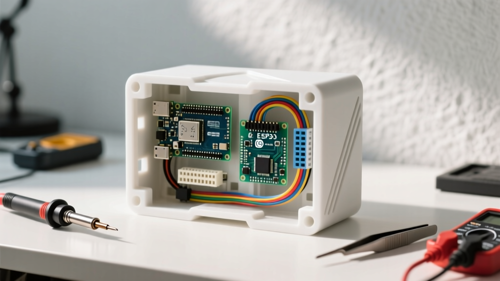
A well-optimized Arduino box is not just a hollow shell; it is a structured ecosystem. To maximize your assembly speed and maintenance efficiency, implement the following internal standards:
1. Ditch the Screw Terminals for Lever Nuts
Soldering wires directly to an Arduino or using tiny screw terminals is a massive workflow bottleneck. In 2026, professional makers have largely migrated to WAGO 221 lever-nut connectors. By mounting a WAGO 221-412 (2-conductor) or 221-413 (3-conductor) block inside your box using the dedicated mounting adapter, you can swap out sensors or power supplies in seconds without a screwdriver. This reduces wiring errors and speeds up field replacements.
2. Standardize Your Standoffs
Never rely on double-sided tape or hot glue to secure your microcontroller. Use brass standoffs to ensure a reliable ground connection and prevent mechanical stress on the USB port.
- Arduino Uno / Mega: Use M3x10mm standoffs. The mounting holes are exactly 3.2mm in diameter.
- Arduino Nano / Pro Mini: These boards lack standardized mounting holes. Design a 3D-printed 'sled' that snaps into standard M3 standoffs, allowing you to slide the Nano in and out without unscrewing anything.
3. Panel Mount Connectors
Routing raw USB cables through a drilled hole leads to cable failure and accidental disconnects. Instead, use panel-mount extensions. A panel-mount USB-B to Micro-USB adapter (requiring a 12mm circular cutout) or a panel-mount DC barrel jack (requiring an 8mm cutout) keeps the exterior of your Arduino box clean and professional.
Step-by-Step: Building a Reusable Sensor Box
Follow this optimized workflow to build a modular, field-ready Arduino enclosure in under 45 minutes.
- Prepare the Baseplate: Cut a 2mm thick acrylic or FR4 sheet to 110 x 70 mm. This acts as your internal chassis. Drill four M3 clearance holes in the corners to match the enclosure's base pillars.
- Mount the Microcontroller: Secure your Arduino to the baseplate using M3x12mm brass standoffs. Ensure the USB port faces the designated cutout side.
- Install Power Distribution: Snap a WAGO 221-413 lever nut block onto the baseplate. Wire your main 12V or 5V input here, then route jumper wires to the Arduino's VIN and GND pins.
- Cut the I/O Ports: Use a step drill bit (4-12mm range) to create clean, burr-free holes for your panel-mount connectors. Pro Tip: Place painter's tape over the ABS plastic before drilling to prevent the bit from catching and cracking the enclosure.
- Cable Management: Use adhesive-backed cable tie mounts (10x10mm) to route sensor wires away from the microcontroller's crystal oscillator to prevent EMI interference.
Thermal Management and EMI Shielding
When enclosing an Arduino, thermal dynamics change drastically. The onboard AMS1117-5.0 linear voltage regulator on an Arduino Uno or Nano will generate significant heat if you are stepping down from 12V to 5V while drawing more than 200mA.
Calculating Thermal Load:
Power Dissipated = (Vin - Vout) x Current.
If Vin = 12V, Vout = 5V, and Current = 0.3A, the regulator dissipates (12 - 5) x 0.3 = 2.1 Watts. In a sealed plastic Arduino box, this will trigger the regulator's thermal shutdown within minutes.
Solutions for Sealed Enclosures
- Switch to Buck Converters: Bypass the onboard linear regulator entirely. Use a miniature DC-DC buck converter (like the Pololu D24V5F5) to step down external power to 5V before feeding it directly into the Arduino's 5V pin. This operates at >85% efficiency, generating almost zero heat.
- Convection Vents: If you must use the linear regulator, mill two 5mm x 20mm slots on the lower-left and upper-right sides of the enclosure to promote passive cross-flow ventilation.
- EMI Shielding: For projects involving RF modules (like the nRF24L01 or LoRa), plastic enclosures offer no electromagnetic interference protection. If you must use plastic, line the inside of the Arduino box with copper foil tape, ensuring the tape is grounded to the Arduino's GND plane.
For a deeper understanding of environmental protections, review the NEMA and IP rating guidelines to ensure your chosen enclosure can withstand the specific humidity and dust levels of your deployment zone.
Conclusion: The ROI of a Standardized Arduino Box
Optimizing your Arduino box workflow is not just about aesthetics; it is about engineering repeatability. By standardizing your enclosure dimensions, adopting lever-nut terminations, and utilizing modular internal baseplates, you transform the most frustrating part of hardware development into a streamlined, 15-minute assembly process. Whether you are deploying a single weather station or manufacturing a batch of 50 custom data loggers, a well-designed enclosure is the hallmark of a mature engineering workflow.