
Why Your Arduino H-Bridge is Failing: A Diagnostic Approach
Integrating an Arduino H-bridge into a robotics or automation project is a rite of passage for makers, but it is rarely plug-and-play. Whether you are driving a pair of 12V DC gearmotors for a rover or controlling a single high-torque linear actuator, H-bridge motor drivers are subjected to extreme electrical stress. When they fail, the symptoms are often misdiagnosed as faulty code or bad Arduinos, when the root cause lies in power delivery, logic level mismatches, or thermal shutdown.
This troubleshooting guide moves beyond basic wiring diagrams. We will dissect the exact failure modes of the most popular motor driver ICs on the market in 2026—including the STMicroelectronics L298N, Texas Instruments L293D, Toshiba TB6612FNG, and TI DRV8833—and provide actionable, multimeter-verified fixes to get your motors spinning reliably.
Component Profiling: Know Your H-Bridge Architecture
Before probing with a multimeter, you must understand the internal architecture of your specific driver. The voltage drop and thermal characteristics vary wildly between older Bipolar Junction Transistor (BJT) designs and modern MOSFET-based drivers.
| Driver IC | Architecture | Typical Voltage Drop | Continuous Current | 2026 Avg. Price (Genuine) |
|---|---|---|---|---|
| L298N | BJT (Darlington) | 1.8V - 2.5V | 2A per channel | $8.50 - $12.00 |
| L293D | BJT (Darlington) | 1.4V - 2.0V | 600mA per channel | $3.00 - $4.50 |
| TB6612FNG | MOSFET | 0.5V (at 1A) | 1.2A per channel | $6.00 (Pololu Carrier) |
| DRV8833 | MOSFET | 0.6V (at 1A) | 1.5A per channel | $2.50 - $4.00 |
Note: Clone L298N modules from generic marketplaces often use substandard Darlington pairs that exhibit voltage drops up to 3.5V under load, severely limiting motor torque.
Symptom 1: Motor Hums or Jitters but Won't Spin
This is the most common issue when using the classic L298N module with a 5V or 6V battery pack. The motor receives enough current to energize the coils (causing a hum) but lacks the voltage to overcome the static friction and start rotating.
The Root Cause: Darlington Voltage Drop
The L298N uses Darlington transistor pairs to switch power. This design inherently drops about 2V across the IC. If you supply 5V to the VCC terminal, the motor only receives 3V. Furthermore, the onboard 5V voltage regulator on cheap clone modules often requires a minimum of 6.5V input to function, meaning your Arduino logic might also be starving.
The Fix: Overcoming the Drop
- Upgrade the Power Supply: Use a 2S LiPo (7.4V nominal) or a 9V battery pack. Supply 8V to 12V to the L298N VCC screw terminal. The motor will receive 6V to 10V, providing ample starting torque.
- Switch to MOSFET Drivers: If your project constraints strictly limit you to a 4.5V to 6V supply (e.g., 4x AA batteries), abandon the L298N. Migrate to a TB6612FNG carrier board. Its low Rds(on) MOSFETs will drop only ~0.2V, delivering nearly the full battery voltage to the motor.
- Verify PWM Duty Cycle: If using
analogWrite(), ensure your duty cycle isn't too low. A value ofanalogWrite(pin, 80)on a 5V system with a 2V drop might not provide enough average voltage to start the motor. Test with255(100% duty cycle) to isolate the issue.
Symptom 2: Arduino Resets or Brownouts When Motor Starts
If your Arduino Uno or Nano instantly reboots, freezes, or drops its serial connection the moment the motor engages, you are experiencing a brownout caused by voltage sag or back-EMF injection.
The Root Cause: Ground Loops and Back-EMF
DC motors are massive inductive loads. When they start, they draw stall current (often 5x to 10x the running current). This massive current draw through thin breadboard wires causes a voltage drop across the ground path. If the Arduino and the motor driver share a long, thin ground wire, the Arduino's ground reference spikes upward relative to its 5V rail, triggering the ATmega328P's internal brown-out detection (BOD) and forcing a reset.
Additionally, when the H-bridge switches off, the collapsing magnetic field in the motor generates a high-voltage reverse spike (back-EMF). If the driver lacks adequate flyback diodes, or if the routing is poor, this spike couples into the Arduino's logic pins.
The Fix: Star Grounding and Decoupling
- Implement Star Grounding: Never daisy-chain your grounds. Run a thick wire (minimum 18 AWG) from the battery's negative terminal directly to the motor driver's high-current GND pin. Run a separate, thinner wire from that exact same battery terminal to the Arduino's GND pin. This prevents high motor currents from flowing through the Arduino's ground path.
- Add Bulk Capacitance: Solder a 100µF to 470µF electrolytic capacitor directly across the VCC and GND screw terminals of the motor driver. This acts as a local energy reservoir to supply the initial stall current without sagging the main battery line.
- High-Frequency Decoupling: Place a 100nF (0.1µF) ceramic capacitor as close to the motor's physical terminals as possible to suppress high-frequency brush noise that can corrupt Arduino ADC readings.
Symptom 3: The H-Bridge IC is Overheating to the Touch
An L298N or L293D that is too hot to touch (exceeding 70°C / 158°F) is operating inefficiently and is on the verge of thermal shutdown. The L298N features internal thermal shutdown at 150°C, but prolonged operation above 100°C degrades the silicon and melts cheap plastic module headers.
The Root Cause: Exceeding Thermal Dissipation Limits
Power dissipated as heat in a BJT H-bridge is calculated as P = Voltage Drop × Current. If your motor draws 1.5A and the L298N drops 2V, the IC is dissipating 3 Watts of heat. The standard TO-220 package without an adequate heatsink has a thermal resistance of roughly 50°C/W to ambient. A 3W dissipation will raise the junction temperature by 150°C above room temperature, instantly triggering thermal shutdown.
The Fix: Thermal Management and Stall Protection
Expert Tip: Never rely solely on the stock aluminum heatsink included with cheap L298N modules. They are often glued on with non-conductive, thermally insulating epoxy that traps heat inside the IC.
- Calculate True Stall Current: Use a multimeter to measure the motor's stall current (lock the rotor and apply rated voltage briefly). If the stall current exceeds 1.5A, the L298N is the wrong tool for the job.
- Implement Software Current Limiting: If your driver supports current sensing (like the TI DRV8833 or the Allegro A4990), route the ISEN pin to an analog input on the Arduino. Read the voltage drop across the sense resistor and programmatically reduce the PWM duty cycle if the current approaches the thermal limit.
- Upgrade the Silicon: For continuous currents above 1.2A, switch to a modern MOSFET driver like the DRV8871 or BTS7960. The BTS7960 handles up to 43A and features a minuscule Rds(on) of 1.6mΩ, virtually eliminating thermal issues at standard maker-scale currents.
Symptom 4: Logic Level Mismatches with 3.3V Arduinos
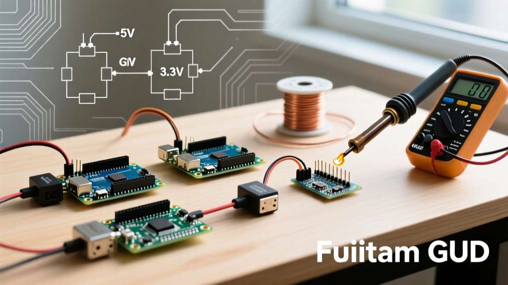
As the maker ecosystem shifts toward 3.3V microcontrollers like the Arduino Nano 33 IoT, ESP32, and Raspberry Pi Pico, driving older 5V logic H-bridges has become a major source of erratic behavior.
The Root Cause: Marginal V_IH Thresholds
The L298N datasheet specifies a High-Level Input Voltage (V_IH) minimum of 2.3V when VCC is 5V. While a 3.3V microcontroller outputs 3.3V, which theoretically clears the 2.3V threshold, breadboard contact resistance and wire voltage drop can easily pull that logic high signal down to 2.1V at the H-bridge pin. This places the input buffer in an undefined linear region, causing the H-bridge to partially turn on both high and low-side transistors—a catastrophic condition known as shoot-through.
The Fix: Proper Level Shifting
- Use a Logic Level Converter: Insert a bidirectional logic level shifter (like the BSS138-based 4-channel modules, costing ~$1.50 in 2026) between the 3.3V Arduino pins and the 5V H-bridge IN1/IN2 pins.
- Opt for 3.3V Native Drivers: The TB6612FNG and DRV8833 natively accept logic voltages down to 2.7V. If using an ESP32 or Pico, bypass the L298N entirely and use these modern ICs to guarantee clean logic switching without extra components.
Advanced Fix: Resolving Motor Whine with PWM Frequency Tuning
If your motors are spinning correctly but emitting an irritating, high-pitched whine, the issue is the Arduino's default PWM frequency. By default, analogWrite() on pins 3, 9, 10, and 11 operates at approximately 490Hz. This frequency falls squarely within the human audible range and causes the motor's internal laminations to vibrate acoustically.
Shifting to Ultrasonic PWM
You can shift Timer 1 (pins 9 and 10 on an Uno/Nano) to an ultrasonic 31.3kHz frequency, rendering the PWM switching completely silent to human ears. Add this line to your setup() function:
// Set Timer 1 to Phase Correct PWM with no prescaler (31.3kHz)
TCCR1B = TCCR1B & B11111000 | B00000001;
Warning: Changing timer prescalers will affect libraries that rely on Timer 1, such as the standard Servo library. If you need both silent motors and servos, use Timer 2 (pins 3 and 11) or migrate to an ESP32, which features dedicated, highly configurable LEDC PWM peripherals.
Final Diagnostic Checklist
Before replacing a suspected dead H-bridge module, run through this 5-step multimeter verification process:
- Measure VCC under load: Place your DMM probes directly on the driver's screw terminals while the motor is commanded to spin. If voltage drops below 80% of the battery's resting voltage, your battery lacks the C-rating or your wires are too thin.
- Verify Logic Highs: Back-probe the IN1 and IN2 pins with the DMM. Ensure you see a clean 4.8V+ (for 5V logic) or 3.2V+ (for 3.3V logic) when the Arduino pin is HIGH.
- Check Enable Pin Voltage: Many clone modules have a jumper on the ENA/ENB pins. Ensure the jumper is firmly seated, or remove it and drive the EN pin directly from a 5V PWM pin on the Arduino for speed control.
- Test for Shoot-Through: If the IC is instantly burning hot with no motor connected, measure the resistance between the motor output terminals (OUT1 and OUT2). A reading near 0Ω indicates the internal H-bridge has shorted and the IC must be replaced.
- Inspect Flyback Diodes: If using a custom board or bare IC, visually inspect the Schottky flyback diodes (e.g., 1N5819). A blown diode will often show a visible crack or read as a dead short across the motor terminals.
By systematically isolating power delivery, logic thresholds, and thermal limits, you can resolve 99% of Arduino motor control issues without resorting to trial-and-error component swapping. Always match the H-bridge architecture to your specific voltage and current constraints, and prioritize clean, star-routed ground topologies in every physical build.