
The Reality of Arduino Robotics Error Diagnosis
Building autonomous platforms is one of the most rewarding applications of microcontrollers, but the transition from a blinking LED to a moving chassis introduces a chaotic layer of electromechanical complexity. In Arduino robotics, code that compiles perfectly on a desktop often fails catastrophically on the bench. Motors twitch, IMUs freeze, and microcontrollers spontaneously reset. These are rarely logic errors; they are physical layer faults masquerading as software bugs.
This guide bypasses basic syntax troubleshooting and dives deep into the hardware-level error diagnosis required to stabilize Arduino-based robots. We will dissect power brownouts, I2C bus lockups, PWM jitter, and encoder bouncing, providing exact component values, diagnostic methodologies, and architectural fixes.
1. Power Distribution & Brownout Resets
The most pervasive failure mode in beginner and intermediate Arduino robotics is the "spontaneous reset." You upload your sketch, the robot initiates a turn, and immediately the Arduino reboots, often losing its state or I2C initialization.
The Root Cause: Stall Current and BOD Thresholds
When a DC motor starts or stalls, it draws its maximum current (stall current), which can easily exceed 1.5A per motor. If you are powering your Arduino Uno R3 and motors from the same 7.4V LiPo battery without adequate decoupling, the sudden voltage sag drops the input to the onboard NCP1117 linear regulator. If the regulated 5V rail dips below the ATmega328P’s Brown-Out Detection (BOD) threshold—typically factory-set to 2.7V or 4.3V depending on the bootloader—the microcontroller triggers a hardware reset to prevent memory corruption.
Diagnostic & Hardware Fixes
- Multimeter Diagnosis: Set your multimeter to capture "Min/Max" voltage on the 5V pin while the motors engage. If you see drops below 4.5V, you have a brownout.
- The Star Ground & Separate Rails Fix: Never route motor return currents through the Arduino's logic ground. Use a 2S LiPo (7.4V) connected to a high-current buck converter (like the LM2596, rated for 3A continuous) dialed to 5.5V for the Arduino logic. Feed the raw 7.4V directly to your motor driver's VMOT pin.
- Capacitor Bank: Solder a 470µF electrolytic capacitor and a 0.1µF ceramic capacitor directly across the motor driver's power input terminals to absorb transient inductive spikes.
2. I2C Bus Lockups in IMUs and LiDAR
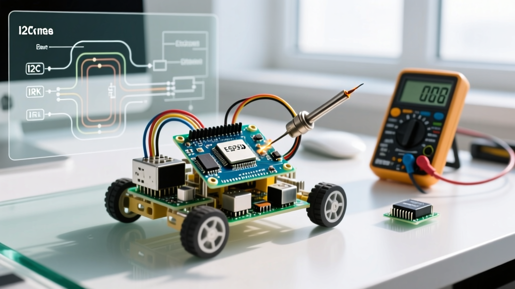
Robots rely heavily on I2C sensors like the MPU6050 (IMU) or VL53L0X (Time-of-Flight). A common catastrophic error is the robot driving blindly because the I2C bus locked up, causing the Wire.endTransmission() function to hang indefinitely.
The Root Cause: SCL Clock Stretching
The ATmega328P's hardware TWI (Two-Wire Interface) peripheral lacks a native timeout mechanism. If a sensor experiences noise and pulls the SCL (clock) line low to "stretch" the clock, the microcontroller waits forever. Furthermore, long wire runs on a robot chassis introduce parasitic capacitance, degrading the square wave edges of the I2C signals.
Diagnostic & Software Fixes
To prevent infinite hangs, modern AVR board packages include a timeout function. Implement this in your setup() block:
Wire.setWireTimeout(3000, true); // Timeout after 3000 microseconds, auto-reset bus
For hardware stabilization, the standard 4.7kΩ pull-up resistors on the SDA and SCL lines are often too weak for 400kHz Fast-Mode I2C on a noisy robot. Drop the pull-up resistors to 2.2kΩ to sharpen the rising edges of the signal. For comprehensive bus protocols, refer to the official Arduino Wire Library documentation.
3. Motor Driver Inefficiencies & PWM Jitter
Choosing the wrong motor driver leads to severe torque loss and audible high-pitch whining, which indicates inefficient PWM switching and thermal throttling.
L298N vs. Modern MOSFET Drivers
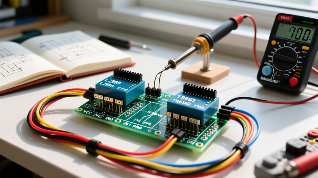
The ubiquitous L298N motor driver is based on old bipolar Darlington transistor technology. It suffers from a massive voltage drop—typically 2.0V at 1A. If you supply it with 7.4V, your motors only receive 5.4V, wasting 30% of your battery energy as heat. Modern robotics demand MOSFET-based drivers like the TB6612FNG (approx. $5-$7) or the DRV8833 (approx. $3-$4), which exhibit a voltage drop of only ~0.5V. For detailed integration steps on the TB6612FNG, consult the SparkFun TB6612FNG Hookup Guide.
Fixing PWM Frequency Jitter
By default, Arduino pins 5, 6, 9, and 10 output PWM at roughly 490Hz. This low frequency causes severe acoustic noise in DC motors and results in "cogging" (jerky movement) at low speeds. To achieve smooth, silent proportional control, use the TimerOne library to push the PWM frequency to 20kHz (ultrasonic range):
Timer1.initialize(50); // 50 microseconds = 20,000 Hz (20kHz)
4. Quadrature Encoder Interrupt Bouncing
Odometry is critical for dead-reckoning in Arduino robotics. However, mechanical quadrature encoders often generate "ghost ticks," causing the robot to calculate incorrect distances and drift over time.
The Root Cause: Contact Bounce
Mechanical encoder switches bounce for milliseconds upon state transitions. If you use attachInterrupt() on the encoder pins, a single physical detent can trigger 5 to 10 interrupts, wildly inflating your tick count.
Diagnostic & Hardware Fixes
- Software Polling (Inefficient): Using
delay()inside an Interrupt Service Routine (ISR) is a cardinal sin in robotics as it halts all background processing. - Hardware RC Filter (Recommended): Build a simple low-pass RC filter for each encoder channel. Place a 10kΩ resistor in series with the signal line, and a 0.1µF ceramic capacitor from the microcontroller input pin to ground. This creates a cutoff frequency of ~160Hz, effectively smoothing out high-frequency bounce while allowing the encoder pulses to pass cleanly.
- State Validation: Inside your ISR, read both Channel A and Channel B. Only increment your tick counter if the phase relationship matches the expected direction matrix.
5. Ground Loop Noise in Ultrasonic Sensors
The HC-SR04 ultrasonic sensor is a staple for obstacle avoidance, but on a moving robot, it frequently returns erroneous 0 cm or 300 cm (timeout) values.
The Root Cause: Acoustic and Electrical Noise
The HC-SR04 measures distance by timing the width of the ECHO pulse. Motor brushes generate massive broadband electromagnetic interference (EMI). This EMI couples into the 5V logic rail and the ECHO signal wire, causing the Arduino's pulseIn() function to trigger prematurely or time out entirely. Furthermore, the physical vibration of the chassis can cause acoustic multipathing.
Diagnostic & Hardware Fixes
To isolate the sensor from chassis noise, mount the HC-SR04 on a silicone dampening pad. Electrically, you must decouple the sensor's power. Solder a 100µF electrolytic capacitor directly across the VCC and GND pins on the back of the HC-SR04 PCB. This local energy reservoir prevents motor-induced voltage sags from resetting the sensor's internal oscillator mid-measurement. For advanced motor grounding techniques and EMI mitigation, the Pololu Motor Driver User Guides provide excellent PCB layout and wiring topology references.
Robotics Diagnostic Matrix
Use this rapid-reference matrix to isolate faults when your Arduino robot exhibits erratic behavior on the bench.
| Symptom | Probable Root Cause | Hardware Diagnostic Tool | Actionable Fix |
|---|---|---|---|
| Arduino resets when motors engage | Voltage sag triggering BOD | Multimeter (Min/Max mode) | Separate logic/motor power; add 470µF bulk capacitor |
| IMU/LiDAR freezes mid-loop | I2C SCL clock stretching | Oscilloscope (Check SCL edges) | Implement Wire.setWireTimeout(); use 2.2kΩ pull-ups |
| Motors whine loudly at low speed | 490Hz default PWM frequency | Auditory / Oscilloscope | Use TimerOne library to set PWM to 20kHz |
| Odometry distance is inflated | Encoder contact bounce | Logic Analyzer | Add 10kΩ/0.1µF RC hardware filter to signal lines |
| Ultrasonic returns 0cm randomly | EMI corrupting ECHO pulse | Oscilloscope on ECHO pin | Add 100µF local decoupling cap on sensor VCC/GND |
Conclusion: Design for the Physical Layer
Successful Arduino robotics requires treating the microcontroller not just as a brain, but as a sensitive node in a high-noise, high-current electromechanical system. By diagnosing errors at the power distribution, signal integrity, and timing levels, you transition from writing code that "sometimes works" to engineering robust, competition-ready robotic platforms.