
The Ultimate Quick-Reference Guide to the Arduino CNC Shield
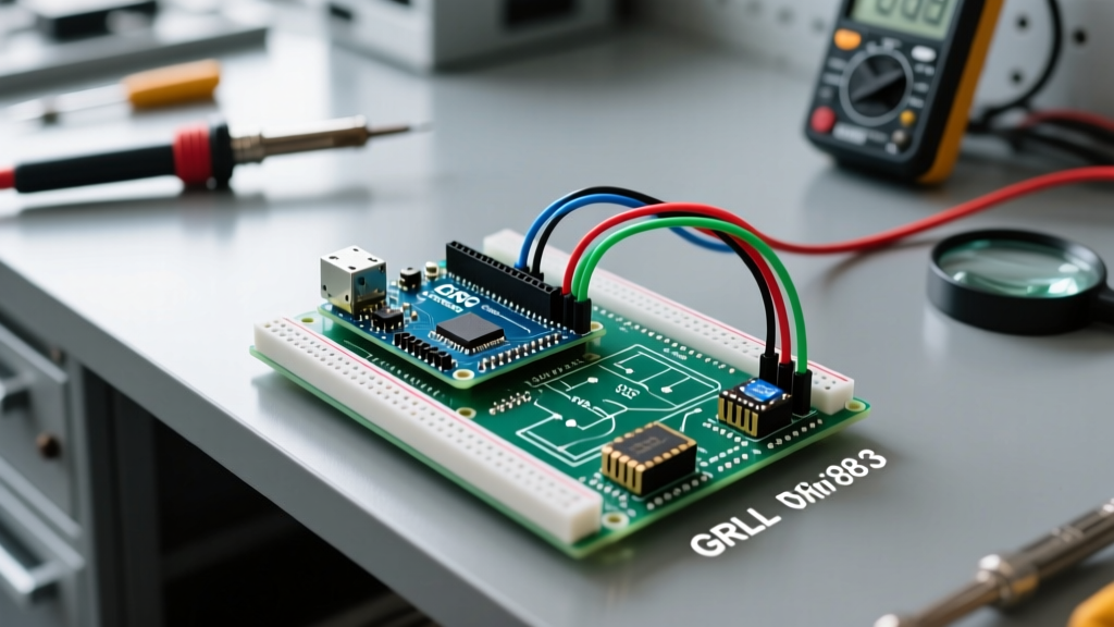
The Arduino CNC Shield V3, originally designed by Protoneer, remains the most cost-effective and widely deployed motion control interface for DIY CNC routers, laser engravers, and plotters. Paired with an Arduino Uno and the GRBL firmware, it translates G-code into precise stepper motor pulses. However, the market is currently flooded with cheap clones that omit critical safety components, leading to widespread confusion regarding wiring, driver tuning, and firmware configuration.
This FAQ and quick-reference guide cuts through the noise, providing exact pinouts, mathematical formulas for current tuning, and edge-case troubleshooting for modern maker setups in 2026.
Core Pinout & Wiring Matrix
The shield maps specific Arduino Uno digital and analog pins to motion and auxiliary functions. Below is the definitive hardware mapping for GRBL 1.1h.
| Function | Arduino Pin | Shield Label | Notes & GRBL Config |
|---|---|---|---|
| X-Axis Step / Dir | D2 / D5 | X-STEP / X-DIR | Standard pulse/direction outputs. |
| Y-Axis Step / Dir | D3 / D6 | Y-STEP / Y-DIR | Standard pulse/direction outputs. |
| Z-Axis Step / Dir | D4 / D7 | Z-STEP / Z-DIR | Standard pulse/direction outputs. |
| A-Axis (Clone) | D12 / D13 | A-STEP / A-DIR | Requires GRBL compile-time modification. |
| Spindle Enable (PWM) | D11 | SpnEn | Outputs 5V PWM for spindle/laser control. |
| Spindle Direction | D13 | SpnDir | Used for reversible DC spindles or VFDs. |
| Coolant / Mist | D12 | Coolant | Toggle for relays controlling air/water mist. |
| Feed Hold | D9 | Hold | Active LOW. Pauses motion gracefully. |
| Cycle Start / Resume | D9 | Resume | Active LOW. Resumes from Feed Hold. |
| Abort / Reset | A0 (Reset) | Abort | Triggers GRBL ALARM state immediately. |
| Limit Switches (X,Y,Z) | A1, A2, A3 | X-Lim, Y-Lim, Z-Lim | Active LOW. Wire between Signal and GND. |
Hardware FAQ: Stepper Drivers & Power Delivery
Which Stepper Driver Should I Use: A4988, DRV8825, or TMC2209?
- A4988: The baseline standard. Supports up to 1/16 microstepping and ~1A continuous current without active cooling. Ideal for small laser engravers and pen plotters. Cost: ~$1.50 per unit.
- DRV8825: The direct upgrade. Supports 1/32 microstepping and handles up to 1.5A continuous (with heatsinks). Better thermal performance for NEMA 17 motors on desktop CNC routers. Cost: ~$2.50 per unit.
- TMC2209: The silent option. Uses StealthChop for near-zero acoustic noise. Warning: The standard V3 shield does not route UART pins to the driver sockets. To use TMC2209s in UART mode for dynamic current tuning, you must manually solder jumper wires from the driver's TX/RX pads to the Arduino's software serial pins. Otherwise, they operate in legacy step/dir mode via hardware jumpers.
How Do I Correctly Tune the VREF Potentiometer?
Setting the current limit (VREF) incorrectly is the number one cause of missed steps and melted drivers. You must measure the voltage at the potentiometer wiper using a digital multimeter while the shield is powered via USB (motors disconnected).
For A4988 Drivers (Standard Clone with 0.1Ω Sense Resistor):
Formula: Vref = Imax × 8 × Rsense. Since Rsense is 0.1Ω, the formula simplifies to Vref = Imax × 0.8.
Example: For a NEMA 17 rated at 1.2A, target VREF = 1.2 × 0.8 = 0.96V.
For DRV8825 Drivers:
Formula: Vref = Imax / 2.
Example: For a NEMA 17 rated at 1.5A, target VREF = 1.5 / 2 = 0.75V.
CRITICAL HARDWARE WARNING: Many sub-$15 clone shields from online marketplaces omit the 100µF electrolytic capacitors across the VMOT and GND pins of each driver socket. According to Pololu's official A4988 documentation, these capacitors are mandatory to absorb inductive voltage spikes. If your shield lacks them, solder 100µF 35V capacitors directly to the shield's power rails before connecting 24V, or risk destroying the Arduino's 5V linear regulator.
GRBL Firmware FAQ: Flashing & Configuration
Why Does the GRBL Upload Fail with 'avrdude: stk500_recv()'?
This is the most common roadblock when flashing GRBL to the Arduino Uno via the Arduino IDE. The CNC Shield V3 routes the Serial TX/RX lines (D0 and D1) directly to the stepper driver enable pins and limit switches depending on the board revision.
The Fix: You must physically remove the CNC Shield from the Arduino Uno (or at least pull all stepper drivers and disconnect the USB) before uploading the grblUpload.ino sketch. The shield's circuitry creates parasitic capacitance and signal contention on the UART lines, preventing the ATmega328P bootloader from syncing with the PC.
Essential GRBL $Settings for CNC Routers
Once flashed, connect via a sender like Universal Gcode Sender (UGS) or Candle. Type $$ to view settings. Below are the baseline parameters for a standard 3018-style CNC router using 1/16 microstepping and 8mm lead screws (2mm pitch).
| Parameter | Description | Typical Value |
|---|---|---|
| $0 | Step pulse time (microseconds) | 10 |
| $1 | Step idle delay (milliseconds) | 25 (Keeps motors locked) |
| $5 | Limit pins invert (0=NC, 1=NO) | 0 (Assuming Normally Closed switches) |
| $100, $101, $102 | X, Y, Z Steps per millimeter | 400.000 (For 2mm pitch, 1/16 step) |
| $110, $111, $112 | X, Y, Z Max rate (mm/min) | 1500.000 |
| $120, $121, $122 | X, Y, Z Acceleration (mm/sec^2) | 50.000 |
| $130, $131, $132 | X, Y, Z Max travel (mm) | Set to your machine's physical limits |
For a complete breakdown of compile-time options and runtime configurations, refer to the official GRBL v1.1 Wiki on GitHub.
Troubleshooting Edge Cases & Failure Modes
1. Motors Jitter or Vibrate Without Moving
Cause: The step pulse width is too short for the driver, or the microstepping jumpers under the drivers are mismatched with the GRBL steps/mm calculation.
Solution: Increase $0 (Step pulse time) from 10 to 30 microseconds. Verify that the physical jumpers on the shield (M0, M1, M2) match your intended microstepping mode. For 1/16 stepping on an A4988, all three jumpers must be installed.
2. Machine Loses Position Mid-Carve (Missed Steps)
Cause: Mechanical binding, aggressive acceleration, or VREF set too low.
Solution: First, reduce $120 (Acceleration) by 50%. If the issue persists, check the VREF voltage. If the driver is overheating (too hot to touch for more than 2 seconds), it is entering thermal shutdown. Lower the VREF by 0.1V and attach an aluminum heatsink with thermal adhesive tape.
3. Limit Switches Trigger Randomly During Spindle Operation
Cause: Electromagnetic interference (EMI) from the spindle motor or VFD coupling into the unshielded limit switch wires.
Solution: GRBL relies on the Arduino's internal pull-up resistors (approx. 20kΩ), which makes the high-impedance analog pins highly susceptible to noise. Solder 0.1µF ceramic capacitors between each limit signal pin (A1, A2, A3) and GND directly on the shield to create a hardware low-pass filter. Additionally, route limit switch cables at least 4 inches away from spindle power cables.
4. Z-Axis Drops When the Machine is Powered Off
Cause: Stepper motors have zero holding torque when unpowered. Gravity pulls the Z-axis down, ruining your Z-zero datum.
Solution: This is a mechanical design flaw, not a shield issue. Upgrade to a Z-axis motor with an electromagnetic brake, or install a physical gas spring / counterbalance to offset the weight of the router spindle.
For further hardware schematics and original design files, the Protoneer CNC Shield documentation remains the definitive primary source for understanding the board's copper traces and jumper logic.