
The Anatomy of Arduino Serial Failures
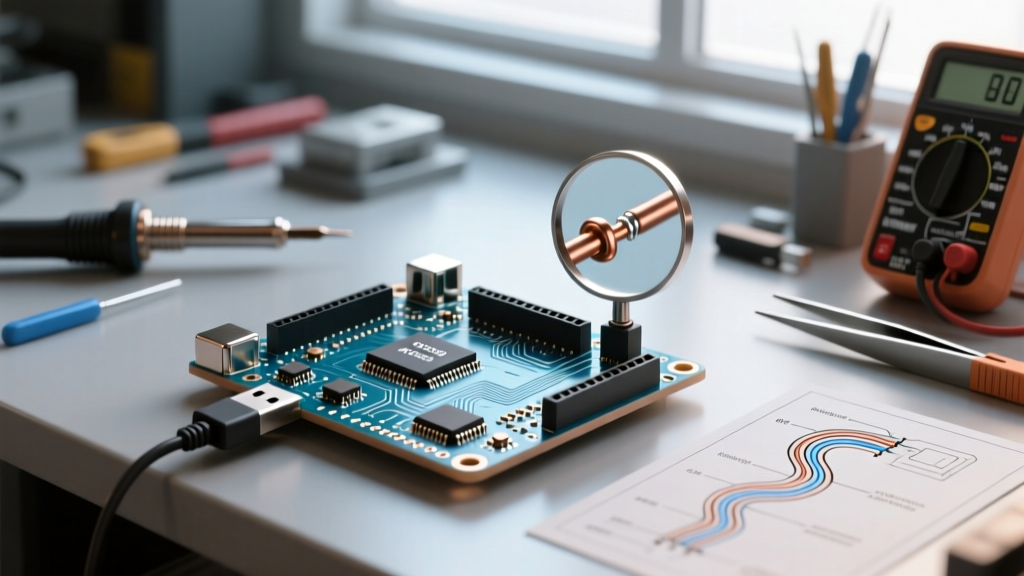
Serial communication remains the undisputed backbone of microcontroller debugging, peripheral integration, and data logging. However, when your arduino communication serial link drops bytes, prints gibberish to the console, or outright refuses to accept sketch uploads, development grinds to a halt. Serial failures rarely stem from a single cause; they are usually a compounding issue of USB driver conflicts, hardware UART voltage mismatches, or baud rate clock drift.
This comprehensive troubleshooting guide dissects the exact failure modes of Arduino serial protocols in 2026, moving beyond basic 'check your cables' advice to provide component-level diagnostics, crystal oscillator math, and logic analyzer verification techniques.
Phase 1: Diagnosing USB-to-Serial (Virtual COM) Failures
Before data ever reaches the ATmega328P or ESP32 microcontroller, it must pass through a USB-to-Serial converter chip. If the Arduino IDE Serial Monitor is completely blank or the port is greyed out, the fault lies in the physical USB layer or the converter IC.
The 'Charge-Only' Cable Trap and Port Power Limits
Approximately 40% of all 'dead board' support tickets trace back to charge-only USB cables. These cables lack the D+ and D- data lines required for serial enumeration. The Fix: Always test with a verified data-sync cable. Furthermore, if you are plugging an Arduino Mega2560 into an unpowered USB 2.0 hub, the board may fail to initialize the ATmega16U2 serial bridge due to the 500mA current limit. Connect directly to a motherboard rear I/O port or a powered USB 3.0 hub.
CH340 vs. ATmega16U2 Driver Conflicts
Genuine Arduino boards utilize the ATmega16U2 chip for USB-to-Serial conversion, while budget-friendly clones typically use the WCH CH340G or the newer CH340C. If Windows Device Manager displays a 'Code 10' or 'Code 43' error under Ports (COM & LPT):
- For CH340 Clones: Windows 11 often auto-installs a generic, incompatible driver. You must manually download the official WCH CH341SER.EXE driver package and force-install it via Device Manager.
- For ATmega16U2: If the board shows up as 'Unknown Device', the 16U2 firmware may be corrupted. You will need to use an external ISP programmer (like a USBasp) to flash the official Arduino USB-Serial firmware hex file back onto the 16U2 chip.
Phase 2: Hardware UART (TX/RX) Troubleshooting
When communicating with external modules like GPS receivers, cellular modems, or secondary microcontrollers, you rely on hardware UART pins (Digital 0 and 1 on an Uno). Hardware UART errors manifest as corrupted characters, framing errors, or total silence.
The Cross-Wiring Rule and Voltage Mismatches
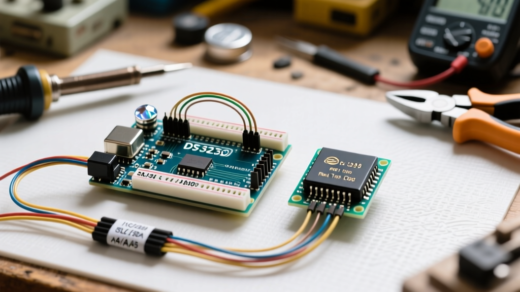
The most common physical layer mistake is wiring TX to TX and RX to RX. Serial communication requires a crossover connection: the Transmitter (TX) of Device A must connect to the Receiver (RX) of Device B, and vice versa. Furthermore, both devices must share a common Ground (GND) reference; without it, the receiver cannot accurately measure the logic high/low voltage thresholds.
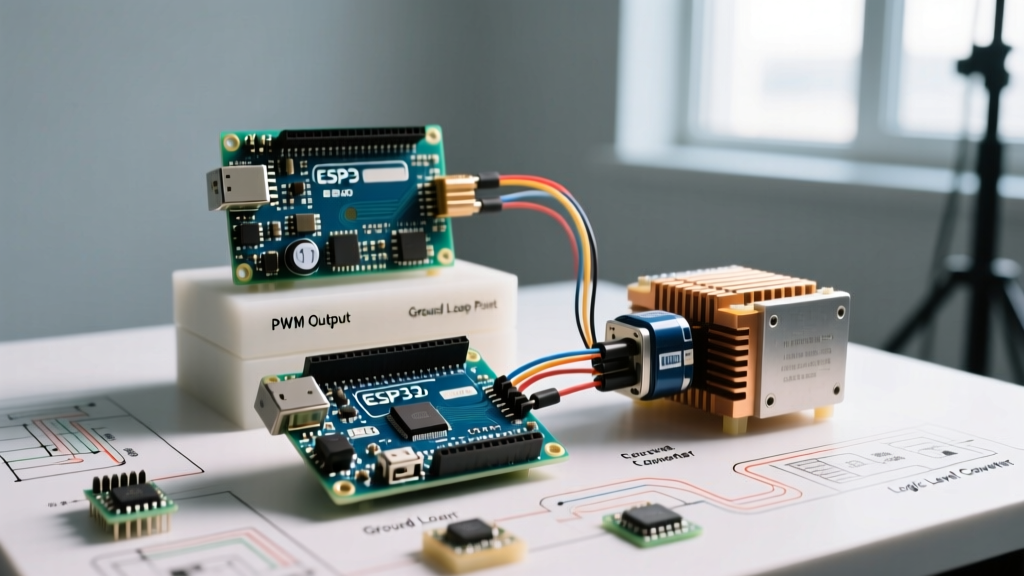
CRITICAL VOLTAGE WARNING: Never connect a 5V Arduino Uno TX pin directly to a 3.3V ESP32 or Raspberry Pi RX pin. While the 3.3V TX to 5V RX direction is usually tolerated, pushing 5V into a 3.3V logic pin will degrade or instantly destroy the silicon. Always use a bidirectional logic level converter (e.g., Texas Instruments TXB0104 or a simple MOSFET-based breakout) when mixing 5V and 3.3V domains.
RS-232 vs. TTL Logic Levels
Standard Arduino UART operates at TTL levels (0V for LOW, 3.3V/5V for HIGH). Legacy industrial equipment and older PC DB9 ports use RS-232 signaling, where a logic LOW is +3V to +15V, and a logic HIGH is -3V to -15V. Connecting an RS-232 cable directly to an Arduino RX pin will fry the microcontroller. You must use a MAX232 or MAX3232 level-shifting IC to invert and step down the voltages safely.
Phase 3: Baud Rate Drift and Crystal Oscillator Math
If your serial monitor outputs readable text interspersed with random garbage characters (e.g., 'Sens?r Rea?ing: 24'), you are experiencing baud rate drift. The Arduino generates serial timing using its main crystal oscillator. If the math doesn't divide evenly into the clock speed, the UART hardware compensates by rounding, introducing a percentage error.
According to the SparkFun Serial Communication Guide, most UART receivers can tolerate up to a ±2% timing error. Exceeding this causes bit-sampling misalignment, resulting in framing errors.
Baud Rate Error Matrix: 16MHz vs. 8MHz Arduino
| Target Baud Rate | 16MHz Crystal Error | 8MHz Crystal Error | Reliability Verdict |
|---|---|---|---|
| 9600 | 0.0% | 0.0% | Flawless |
| 38400 | 0.8% | -0.8% | Safe |
| 57600 | -2.1% | 2.1% | Marginal (Risk over long cables) |
| 115200 | -2.1% | -3.5% | Fails on 8MHz (Use 250k instead) |
| 250000 | 0.0% | 0.0% | Flawless (High Speed) |
The Fix: If you are running an 8MHz Arduino Pro Mini and need high-speed logging, avoid 115200 baud. Switch your Serial.begin() to 250000 or 500000, which divide perfectly into 8MHz, yielding a 0.0% error rate.
Phase 4: SoftwareSerial Bottlenecks and Interrupt Conflicts
When hardware UART pins (D0/D1) are occupied, makers often turn to the SoftwareSerial library. However, as noted in the Official Arduino Serial Reference, bit-banging serial data via software is highly resource-intensive and prone to failure at high speeds.
Why SoftwareSerial Fails at 115200 Baud
SoftwareSerial relies on pin-change interrupts and precise microsecond delays to read incoming bits. At 115200 baud, a single bit lasts only 8.68 microseconds. On a 16MHz ATmega328P, that equates to roughly 138 clock cycles per bit. Any background interrupt (like the Timer0 interrupt used for millis() or PWM updates) will disrupt this timing, causing the library to sample the wrong bit and corrupt the byte.
Best Practices for Software Serial:
- Cap the Baud Rate: Never exceed 38400 baud when using SoftwareSerial on an AVR-based board.
- Use AltSoftSerial: If you must use software serial, the
AltSoftSeriallibrary utilizes hardware timers instead of blocking delays, allowing simultaneous reception and transmission without breaking PWM or I2C. - Upgrade the Hardware: If your project requires multiple high-speed serial streams (e.g., a GPS at 9600 and a 4G LTE modem at 115200), abandon the Uno. Upgrade to an Arduino Mega2560, which features four dedicated hardware UARTs, or an ESP32, which allows flexible UART pin mapping via the GPIO matrix.
Essential Debugging Tools for Serial Sniffing
When the Serial Monitor fails to reveal the issue, you must inspect the raw electrical signals. Relying solely on code-based debugging is insufficient for complex hardware integration.
Logic Analyzers over Oscilloscopes
While an oscilloscope is excellent for checking voltage levels and rise times, a USB Logic Analyzer is vastly superior for decoding serial protocols. Devices like the Saleae Logic 8 or the budget-friendly DreamSourceLab DSLogic Plus can sample at 24 MS/s (Mega-samples per second) or higher.
By connecting the logic analyzer probe to the TX line and setting a trigger on the falling edge of the start bit, the software will automatically decode the hex/ASCII payload. This allows you to definitively prove whether the microcontroller is transmitting the correct data, or if the receiving peripheral is rejecting it due to a parity or stop-bit mismatch.
Summary Checklist for Serial Recovery
Before tearing apart your circuit, run through this rapid diagnostic sequence:
- Layer 1 (Physical): Verify data-capable USB cable; confirm TX-to-RX crossover; check shared GND.
- Layer 2 (Electrical): Measure TX/RX idle states with a multimeter (should read 3.3V or 5V HIGH when idle).
- Layer 3 (Protocol): Match baud rates exactly; verify 8N1 (8 data bits, No parity, 1 stop bit) configuration.
- Layer 4 (Software): Ensure no other libraries are disabling interrupts; flush the serial buffer using
Serial.flush()before sleep modes.
By systematically isolating the fault domain—from the USB bridge IC down to the crystal oscillator math—you can resolve virtually any arduino communication serial failure and restore reliable data flow to your embedded systems.
For deeper insights into optimizing memory and logging, refer to the Adafruit Serial Logging Guide to implement non-blocking ring buffers in your sketches.