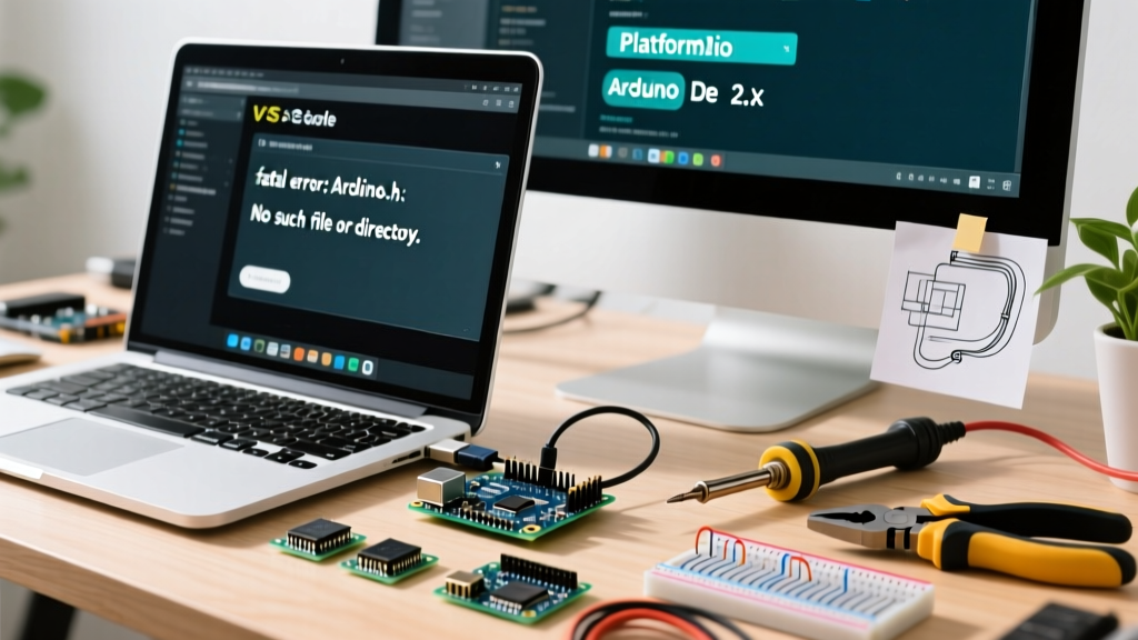

The Anatomy of the INPUT_PULLUP Arduino Error
When interfacing mechanical switches, pushbuttons, or limit sensors with a microcontroller, the INPUT_PULLUP configuration is a staple of modern embedded design. By enabling the internal pull-up resistor via pinMode(pin, INPUT_PULLUP);, you eliminate the need for external resistors on the breadboard, wiring the switch directly between the GPIO pin and ground. In theory, the pin reads HIGH when the switch is open and LOW when closed. In practice, however, makers frequently encounter erratic serial monitor spam, phantom triggers, and unresponsive inputs.
Diagnosing these INPUT_PULLUP Arduino errors requires moving beyond basic code syntax and understanding the underlying physics of high-impedance nodes, parasitic capacitance, and electromagnetic interference (EMI). This guide provides a deep-dive diagnostic framework for identifying and resolving floating pin anomalies across AVR, ESP32, and RP2040 architectures.
The Physics of the Floating Pin and the 'Antenna Effect'
A floating pin occurs when a GPIO is configured as an input but lacks a defined DC path to either VCC or GND. Without a pull-up or pull-down resistor, the pin's impedance is exceptionally high (often exceeding 100 MΩ). In this state, the silicon gate acts as a high-gain antenna. According to SparkFun's electronics tutorials, a floating pin will capacitively couple with nearby alternating electric fields, particularly 50Hz/60Hz mains hum from nearby AC wiring, switching power supplies, or unshielded motor drivers.
When you rely on the microcontroller's internal pull-up resistor, you are typically working with a resistance value between 20kΩ and 50kΩ. While this is sufficient to pull the pin to VCC in a quiet environment, it forms a voltage divider with any leakage paths or capacitive coupling in noisy industrial or automotive environments, leading to the dreaded 'ghost reads'.
Diagnostic Matrix: Symptom to Root Cause
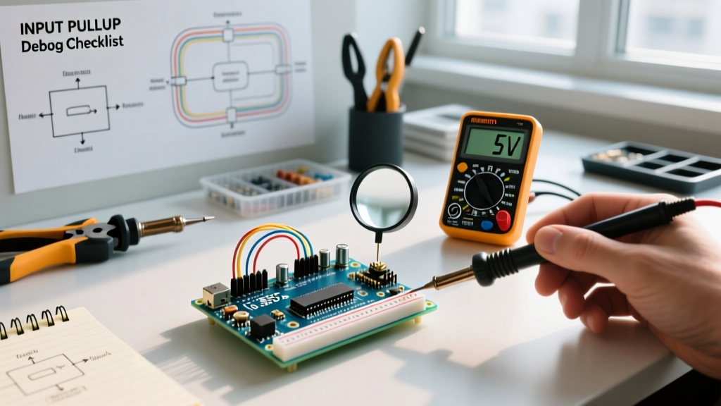
Before swapping out microcontrollers or rewriting your debounce logic, use a digital multimeter (DMM) or an oscilloscope to measure the voltage at the GPIO pin relative to GND while the circuit is in its 'open' (unpressed) state. Match your readings to the diagnostic matrix below.
| Observed Symptom | DMM / Scope Reading | Root Cause | Actionable Fix |
|---|---|---|---|
| Random HIGH/LOW spam in Serial Monitor | Fluctuating 1.2V - 3.8V | Floating pin / Severe EMI coupling | Add 10kΩ external pull-up; shield cables; route away from AC lines |
| Input always reads HIGH | Steady 5.0V or 3.3V | Switch wired to VCC instead of GND | Rewire switch between GPIO Pin and GND (Active-LOW logic) |
| Input always reads LOW | 0.0V - 0.1V | Short to GND or damaged silicon gate | Check for solder bridges, flux residue, or test continuity to GND |
| Delayed state change / missed interrupts | Slow exponential voltage ramp | Parasitic capacitance (long wire runs) | Lower pull-up resistance to 4.7kΩ or 2.2kΩ external |
| Intermittent triggers without touching switch | Sharp nanosecond voltage dips | Switch bounce or mechanical vibration | Implement software debouncing or add 100nF capacitor in parallel |
Microcontroller Internal Pull-Up Specifications
A common misconception is that all internal pull-up resistors are identical. The actual resistance varies significantly depending on the silicon process and the specific MCU family. Understanding these values is critical when calculating RC time constants for long wire runs or when interfacing with external logic families. The official Arduino pinMode() reference notes that AVR internal pull-ups are generally in the 20kΩ to 50kΩ range, but let us look at the exact specifications for popular maker boards.
- ATmega328P (Arduino Uno/Nano): Typical 32kΩ (Range: 20kΩ - 50kΩ). Powered at 5V, this provides roughly 150µA of current when shorted to GND.
- ESP32 (Standard & S3): Typical 45kΩ. Note that the ESP32 lacks internal pull-down resistors on most GPIOs, making
INPUT_PULLUPthe default and safest choice for button inputs. - RP2040 (Raspberry Pi Pico): Typical 50kΩ - 60kΩ. Because the Pico operates at 3.3V logic, the weak internal pull-up can be easily overpowered by long-wire capacitance or minor leakage currents.
- STM32F103 (Blue Pill): Typical 30kΩ - 50kΩ. Highly susceptible to noise if used in unshielded environments without external reinforcement.
The Long-Wire Capacitance Trap
One of the most complex INPUT_PULLUP Arduino errors occurs when a switch is located far from the microcontroller. Standard hook-up wire or coaxial cable possesses parasitic capacitance, typically around 100pF per meter. If you run a 5-meter cable to a limit switch, you introduce 500pF of capacitance to ground.
When the switch opens, the internal 32kΩ pull-up resistor must charge this 500pF capacitor. The RC time constant (τ = R × C) becomes 16 microseconds. While this seems fast, in an environment with high-frequency EMI (like near a stepper motor driver), the slow rising edge spends too much time in the microcontroller's undefined logic threshold region (typically between 1.5V and 3.0V for 5V AVR logic). This causes the input buffer to oscillate wildly, generating dozens of false interrupts. The fix: Bypass the weak internal pull-up and install a strong 4.7kΩ or 2.2kΩ external resistor at the microcontroller pin to drastically reduce the RC time constant.
Ghost Reads vs. Switch Bounce: A Diagnostic Distinction
Makers frequently conflate 'ghost reads' caused by poor pull-up configurations with mechanical 'switch bounce'. Both result in multiple triggers from a single button press, but their diagnostic signatures are entirely different.
Expert Diagnostic Tip: If your serial monitor shows input triggers occurring randomly while the button is completely untouched, you are dealing with a floating pin or EMI issue (Ghost Reads). If the erratic triggers only occur in the exact millisecond the button is physically pressed or released, you are dealing with mechanical contact bounce.
Switch bounce is a mechanical phenomenon where the metal contacts physically chatter before settling. This happens in the 1ms to 5ms timeframe. A pull-up resistor will not fix switch bounce. To resolve bounce, you must implement a software debounce delay (e.g., ignoring state changes for 50ms after an edge is detected) or use a hardware RC low-pass filter combined with a Schmitt trigger inverter like the 74HC14.
Step-by-Step Troubleshooting Workflow
When faced with an unresponsive or erratic INPUT_PULLUP circuit, follow this systematic isolation process:
- Verify Active-LOW Logic: Ensure your code checks for
LOWwhen the button is pressed. A common beginner error is wiring the switch to GND but writingif (digitalRead(pin) == HIGH)in the sketch. - Disconnect External Hardware: Remove the switch and wire entirely. Upload a blink sketch that also reads the pin and prints to the serial monitor. If the pin reads a steady
HIGH, the MCU's internal pull-up is functional. If it fluctuates, the pin may be damaged or suffering from severe board-level leakage (e.g., conductive flux residue under the MCU). - Test Continuity: Use a multimeter in continuity mode. Place one probe on the GND pin and the other on your switch's output terminal. Press the button. You should hear a beep. If you have continuity when the button is NOT pressed, your switch is internally shorted or miswired.
- Inspect for Breadboard Parasitics: Solderless breadboards have high contact resistance and stray capacitance. If your circuit works in simulation (like Wokwi or Tinkercad) but fails on the bench, move the pull-up wiring to a soldered perfboard to rule out breadboard degradation.
- Inject an External Pull-Up: If the environment is electrically noisy, connect a 10kΩ resistor between the GPIO pin and VCC (5V or 3.3V, matching the MCU logic level). This lowers the impedance of the node by a factor of 3 to 5, effectively drowning out capacitively coupled EMI.
Advanced Edge Cases: I2C Bus Conflicts and 3.3V/5V Mismatches
Occasionally, an INPUT_PULLUP error is not isolated to a simple button but occurs when a GPIO is shared with a communication bus or a different voltage domain.
The I2C Bus Collision
The I2C protocol requires pull-up resistors on both SDA and SCL lines. If you attempt to use a pin that is currently acting as an I2C line as a standard INPUT_PULLUP digital read, the internal MCU pull-up will conflict with the external I2C pull-ups (usually 4.7kΩ). Furthermore, if the I2C bus is actively being pulled LOW by a sensor, your digital read will return LOW, leading you to believe a button was pressed. Always ensure pins designated for Wire.h (I2C) or SPI are excluded from your switch matrix.
Voltage Domain Mismatches
If you are using a 3.3V microcontroller (like the ESP32 or Arduino Due) but wiring a switch that pulls the line to a 5V rail when closed (an incorrect active-HIGH setup mistakenly combined with INPUT_PULLUP), you risk back-feeding the 3.3V GPIO through its internal ESD protection diodes. This will cause the pin to permanently read HIGH and may eventually destroy the silicon gate. Always ensure the switch routes to the system GND, allowing the internal pull-up to safely reference the MCU's native VCC.
Summary
Mastering the INPUT_PULLUP configuration requires more than just copying a line of code; it demands an understanding of impedance, capacitance, and environmental noise. By recognizing the physical limitations of internal silicon resistors (typically 20kΩ - 60kΩ) and systematically isolating hardware faults from software logic errors, you can build robust, noise-immune input circuits. For further reading on managing digital logic thresholds and noise margins, consult All About Circuits' comprehensive guide on pull-up resistor applications. When in doubt, reinforce your internal pull-ups with external 10kΩ resistors and implement rigorous software debouncing to ensure flawless operation in the real world.