
The Definitive Guide to Arduino with Zigbee Integration
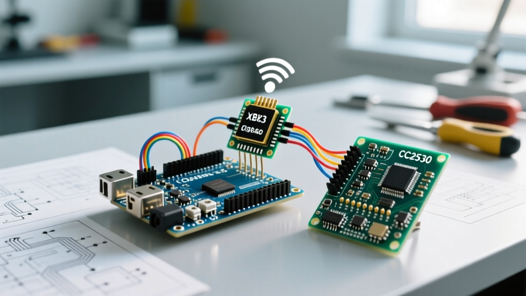
Integrating an Arduino with Zigbee technology remains one of the most robust methods for building low-power, mesh-networked IoT devices in 2026. While newer protocols like Thread and Matter are gaining traction, Zigbee 3.0 (based on IEEE 802.15.4) continues to dominate industrial sensor networks, smart agriculture, and off-grid telemetry due to its exceptional range and mesh-routing capabilities. This configuration guide bypasses basic tutorials and dives directly into professional-grade hardware selection, logic-level protection, and network provisioning for both Digi XBee3 and Texas Instruments CC2530 architectures.
Hardware Selection Matrix: XBee3 vs. CC2530
Choosing the right Zigbee module dictates your development workflow. The Digi XBee3 offers a premium, pre-certified route with AT and API command sets, while the TI CC2530 provides a budget-friendly, bare-metal Z-Stack experience. Below is a comparative analysis of the most relevant modules available on the market.
| Module | Chipset | Avg. Price (2026) | Stack / Firmware | Best Use Case |
|---|---|---|---|---|
| Digi XBee3 (XB3-24Z8PT) | Silicon Labs EFR32 | $48.00 - $55.00 | Digi XBee3 Zigbee 3.0 | Commercial IoT, rapid prototyping |
| Digi XBee S2C (XBP24CZ7) | Silicon Labs EM357 | $35.00 - $42.00 | Zigbee PRO (Legacy) | Maintenance of legacy 2015-2020 systems |
| TI CC2530 (Bare) | TI CC2530F256 | $8.00 - $12.00 | TI Z-Stack 3.0.2 | High-volume hobbyist, budget mesh nodes |
| Ebyte E180-Z8900-SMA | TI CC2530 | $14.00 - $18.00 | TI Z-Stack / Custom | Outdoor telemetry (SMA antenna support) |
Critical Hardware Warning: The 5V vs 3.3V Trap
WARNING: Standard Arduino boards (Uno R3, Mega 2560, Nano) operate at 5V logic. Zigbee modules are strictly 3.3V and are not 5V tolerant. Connecting an Arduino TX pin directly to a Zigbee DIN/RX pin will permanently destroy the module's UART transceiver within milliseconds.
To safely interface a 5V Arduino with a 3.3V Zigbee module, you must use a bidirectional logic level converter. The BSS138 MOSFET-based converter (approx. $2.50) is the industry standard for this task. Wire the Arduino 5V to the HV side, the module 3.3V to the LV side, and route the TX/RX lines through the corresponding channels. Alternatively, migrate to a native 3.3V microcontroller like the Arduino Nano 33 IoT or the MKR WiFi 1010 to eliminate the need for level shifters entirely.
Path 1: Configuring Digi XBee3 via XCTU
The Digi XBee3 is the premier choice for developers who want to avoid compiling complex RF stacks. Configuration is handled via Digi's XCTU software using either transparent (AT) or API mode.
Step-by-Step XCTU Provisioning
- Install and Connect: Download XCTU from the Digi International portal. Mount the XBee3 on a USB explorer board and connect it to your PC.
- Discover and Update: Click Discover Radios. Select your module and update the firmware to the latest Zigbee 3.0 Coordinator or Router build (e.g., version 100A or newer).
- Set API Mode (AP Parameter): For Arduino integration, API mode is vastly superior to transparent mode because it allows the MCU to parse incoming RF payloads and address data. Set
AP=2(API mode with escaped characters) to prevent payload bytes from accidentally triggering UART control sequences. - Define the PAN ID (ID Parameter): Set a unique 16-bit or 64-bit PAN ID. If left at
ID=0, the coordinator will randomly generate one, making it impossible for pre-configured routers to join without a network scan. - Channel Masking (SC Parameter): By default, the module scans all 16 Zigbee channels. To speed up network joining and avoid Wi-Fi interference, set the Scan Channels bitmask to target non-overlapping channels (detailed in the RF Coexistence section below).
Arduino Code Integration
Once provisioned in API mode, use the official digi-xbee Arduino library. Instantiate the XBeeZigBee object, attach it to a SoftwareSerial or hardware UART port, and use the readPacket() method to parse incoming ZBRxResponse frames. This allows your Arduino to extract the 64-bit source address and the specific sensor payload simultaneously.
Path 2: The TI CC2530 and Z-Stack Route
For budget-conscious deployments or high-volume custom PCBs, the TI CC2530 paired with TI Z-Stack is the standard. Unlike the XBee, the CC2530 does not have a simple AT command interface; it requires compiling C code in the IAR Embedded Workbench.
Flashing and Serial Handoff
To use a CC2530 as a Zigbee-to-UART bridge for an Arduino, you must flash a pre-compiled ZNP (Zigbee Network Processor) firmware using a TI CC-Debugger. Once flashed, the CC2530 acts as a dumb modem. The Arduino sends specific UNPI (Unified Network Processor Interface) serial frames to instruct the CC2530 to join networks, bind clusters, and transmit data. While highly customizable, the UNPI protocol requires strict byte-level checksum calculations in your Arduino sketch.
RF Coexistence: Navigating 2.4 GHz Congestion
Zigbee and Wi-Fi both operate in the crowded 2.4 GHz ISM band. A common failure mode in Arduino Zigbee deployments is silent packet loss due to Wi-Fi router interference. Zigbee utilizes channels 11 through 26 (each 2 MHz wide), while Wi-Fi uses channels 1, 6, and 11 (each 22 MHz wide).
| Wi-Fi Channel | Frequency Range | Safe Zigbee Channels (No Overlap) |
|---|---|---|
| Wi-Fi 1 | 2.401 - 2.423 GHz | Zigbee 20, 25, 26 |
| Wi-Fi 6 | 2.426 - 2.448 GHz | Zigbee 11, 12, 13 |
| Wi-Fi 11 | 2.451 - 2.473 GHz | Zigbee 15, 16, 17 |
Actionable Advice: If your deployment environment has an active Wi-Fi network on Channel 1 and Channel 6 (the most common dual-band router default), configure your Zigbee Coordinator's SC parameter to restrict the network to Zigbee Channel 20 or 25. This virtually eliminates physical layer (PHY) collisions.
Advanced Troubleshooting and Edge Cases
- Network Join Timeouts: If an Arduino-configured router fails to join the coordinator, check the
JV(Join Verification) parameter. In Zigbee 3.0, routers should haveJV=1to ensure they verify the coordinator is still operating on the same channel before attempting to join, preventing orphaned nodes. - Sleep Mode UART Desync: When configuring an XBee3 as a sleeping End Device (
SM=4orSM=5), the module powers down its UART to save micro-amps. The Arduino must assert the CTS (Clear to Send) pin or toggle the Sleep_RQ pin to wake the module before pushing serial data, otherwise, the first 3-5 bytes of the payload will be dropped. - PAN ID Conflicts: If two coordinators in proximity share the same PAN ID but different extended PAN IDs, the network will fracture. Always read the Connectivity Standards Alliance Zigbee specifications regarding extended PAN ID generation to ensure compliant network merging behavior.
Summary
Successfully configuring an Arduino with Zigbee requires moving beyond simple serial printing. By selecting the appropriate hardware matrix, strictly enforcing 3.3V logic levels, provisioning API modes via XCTU, and strategically masking RF channels to avoid Wi-Fi interference, you can build a resilient, low-latency mesh network capable of scaling across hundreds of nodes.