
The Anatomy of Failure: Why ESP32 Camera Pinouts Cause Headaches
When working with the AI-Thinker ESP32-CAM or wiring a raw ESP32-WROVER to an OV2640 or OV5640 sensor, the esp32 camera pinout is notoriously unforgiving. Unlike standard SPI or I2C sensors, camera modules rely on an 8-bit parallel data bus, an SCCB (Serial Camera Control Bus) interface, and a high-frequency XCLK clock signal. A single miswired GPIO, a missing pull-up resistor, or a marginal power rail will instantly result in the dreaded Camera init failed with error 0x20001 or a silent bootloop.
This troubleshooting guide bypasses basic copy-paste tutorials and dives straight into the hardware-level failure modes of the ESP32 camera architecture. We will provide exact electrical fixes for the most common pinout and initialization faults encountered by advanced makers and embedded engineers.
AI-Thinker ESP32-CAM GPIO Mapping & Critical Wiring Rules
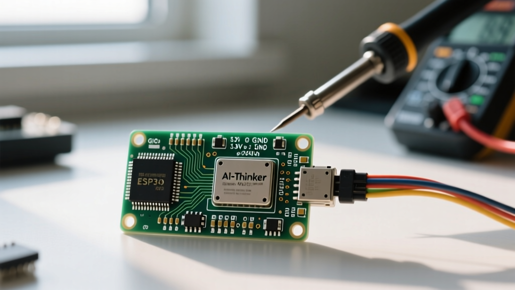
The AI-Thinker ESP32-CAM module integrates an ESP32-S chip with 4MB PSRAM and an OV2640 sensor. Because the ESP32 has a limited number of exposed GPIOs, the official esp32-camera library hardcodes specific pins for the camera interface. If you are designing a custom breakout board or repairing a damaged trace, you must adhere strictly to this mapping.
| Camera Signal | ESP32 GPIO | Function & Troubleshooting Notes |
|---|---|---|
| XCLK | GPIO 0 | 20MHz Master Clock. Warning: GPIO0 is a strapping pin. If pulled LOW during boot, the ESP32 enters flash mode. |
| SIOD (SDA) | GPIO 26 | SCCB Data (I2C). Requires a 4.7kΩ pull-up to 3.3V for reliable OV2640 register reads. |
| SIOC (SCL) | GPIO 27 | SCCB Clock (I2C). Requires a 4.7kΩ pull-up to 3.3V. |
| VSYNC | GPIO 25 | Vertical Sync. Must be routed with minimal trace length to prevent phase skew. |
| HREF | GPIO 23 | Horizontal Reference. |
| PCLK | GPIO 22 | Pixel Clock. High-frequency signal; keep traces short and avoid vias. |
| D0 - D7 | 5, 18, 19, 21, 36, 39, 34, 35 | 8-bit Parallel Data Bus. GPIOs 34-39 are input-only and lack internal pull-ups. |
| PWDN | GPIO 32 | Power Down. Active HIGH. Must be driven LOW for the camera to operate. |
| RESET | GPIO -1 | Hardware Reset. Usually tied to 3.3V via a 10kΩ resistor on the AI-Thinker board. |
Troubleshooting Matrix: Error Codes & Pinout Fixes
When the esp_camera_init() function fails, the ESP32 returns specific hexadecimal error codes. Understanding these codes is the fastest way to isolate a pinout or hardware fault.
Error 0x20001 or 0x105: Camera Probe / Init Failed
This is the most common error. It means the ESP32 successfully allocated memory but failed to communicate with the camera sensor over the SCCB (I2C) bus to read its PID (Product ID).
- The XCLK Strapping Pin Conflict: The camera requires GPIO0 to output a 20MHz clock (XCLK). However, GPIO0 is a boot strapping pin. If you are trying to flash new firmware while the camera is connected, the XCLK line can interfere with the boot mode, causing the ESP32 to hang or the camera to fail initialization upon reboot. Fix: Always disconnect the camera module (or ensure GPIO0 is not pulled low by external circuitry) when pressing the RESET button to enter flash mode.
- Missing I2C Pull-ups: The AI-Thinker ESP32-CAM board often omits external pull-up resistors on GPIO26 (SIOD) and GPIO27 (SIOC), relying entirely on the ESP32's weak internal pull-ups. In noisy environments or with longer FPC cables, this causes I2C corruption. Fix: Solder 4.7kΩ resistors between GPIO26/27 and the 3.3V rail.
- PWDN Pin State: If GPIO32 (PWDN) is left floating or driven HIGH, the OV2640 enters a low-power standby mode and will not respond to I2C probes. Ensure your
camera_config_tstruct setspin_pwdn = 32and the library initializes it LOW.
Brownout Detector Was Triggered
The console prints Brownout detector was triggered and the ESP32 immediately reboots. This is rarely a code issue; it is a catastrophic power delivery failure tied to the pinout's power rails.
The OV2640 sensor draws a baseline of ~120mA, but during initialization and high-resolution capture (e.g., UXGA at 15fps), current spikes can exceed 300mA. The onboard AMS1117-3.3 LDO on the AI-Thinker board has a high dropout voltage and poor transient response. If powered via a standard USB-to-Serial adapter (like a cheap CH340) that only supplies 500mA on the 5V line, the voltage sags below the ESP32's 2.7V brownout threshold.
Expert Hardware Fix: Bypass the onboard LDO entirely. Inject a clean, regulated 3.3V directly into the 3.3V header pin using an external buck converter (like an LM2596 or MP1584) capable of delivering 2A. Add a 100µF low-ESR tantalum capacitor directly across the 3.3V and GND pins near the ESP32-S chip to absorb the camera's transient current spikes.
PSRAM Initialization Failures (Error 0x105)
If the camera initializes but crashes when allocating frame buffers, you are likely hitting a PSRAM boundary issue. The ESP32-CAM uses an integrated 4MB PSRAM chip connected via a dedicated SPI bus on GPIO16 and GPIO17.
A common beginner mistake is attempting to use GPIO16 or GPIO17 for external peripherals (like a secondary I2C bus or UART) while the camera is active. Because these pins are internally routed to the PSRAM die on the ESP32-WROVER/ESP32-S module, any external wiring on these pins will corrupt the PSRAM bus, leading to immediate frame buffer allocation failures. Leave GPIO16 and GPIO17 completely unconnected on your custom PCBs.
The 24-Pin FPC Connector: OV2640 and OV5640 Ribbon Cable Secrets
If you are designing a custom carrier board or replacing a damaged sensor on an ESP32-CAM module, you will interface with the 24-pin, 0.5mm pitch FPC (Flexible Printed Circuit) connector. Misinterpreting this pinout is the leading cause of dead camera sensors.
Ribbon Cable Orientation and the 'Magic Smoke'
The 24-pin FPC connector does not have a universal standard for pin 1 orientation across all manufacturers. On the AI-Thinker board, the connector is surface-mounted, and the ribbon cable contacts face a specific direction. If you flip the ribbon cable 180 degrees:
- You will route 3.3V/2.8V directly into the sensor's GND pins.
- You will reverse the I2C and parallel data buses.
- The camera's internal 1.5V core LDO will instantly short, permanently destroying the OV2640 silicon.
Verification Rule: Always use a multimeter in continuity mode to trace Pin 1 (usually VCC or GND) on the FPC connector back to the schematic before applying power. On the standard OV2640 24-pin module, Pin 1 is typically GND and Pin 2 is SDA, but always verify against the specific datasheet of the sensor module you purchased.
Hardware Fixes: Signal Integrity on the Parallel Bus
When operating at high resolutions (UXGA) or high frame rates, the 8-bit parallel data bus (D0-D7) and the PCLK (Pixel Clock) operate at frequencies up to 20MHz. At these speeds, the ESP32 camera pinout behaves like a high-speed RF transmission line rather than simple DC wiring.
- Trace Length Matching: If you are designing a custom PCB, the trace lengths for D0-D7, PCLK, VSYNC, and HREF should be matched within a 10% tolerance. If PCLK arrives significantly earlier or later than the data lines, the ESP32's I2S peripheral will sample the wrong bit states, resulting in green/pink screen artifacts or horizontal tearing in the image output.
- Series Termination Resistors: To prevent signal ringing on the PCLK and XCLK lines, place 22Ω to 33Ω series termination resistors as close to the ESP32 GPIO pins as possible. This dampens the high-frequency harmonics and drastically reduces the
0x20001initialization errors caused by clock jitter. - Ground Shielding: Ensure a solid ground plane exists directly beneath the FPC connector and the parallel data traces. Refer to the Espressif Hardware Design Guidelines for specific PCB stack-up recommendations regarding high-speed GPIO routing.
Summary Checklist for First-Time Boot
Before uploading the CameraWebServer example sketch, run through this hardware verification checklist:
- Verify the power supply can deliver a minimum of 5V at 2A (if using the 5V pin) or 3.3V at 1A (if bypassing the LDO).
- Confirm GPIO0 is not externally pulled LOW during the boot sequence.
- Ensure GPIO16 and GPIO17 are left floating (reserved for PSRAM).
- Check that the FPC ribbon cable is fully seated and the locking flap is securely closed.
- Add 4.7kΩ pull-up resistors to GPIO26 and GPIO27 if using long wires or a custom breakout.
Mastering the esp32 camera pinout requires respecting both the digital logic levels and the analog power requirements of the image sensor. By addressing the I2C bus integrity, XCLK strapping conflicts, and transient power demands, you can eliminate initialization errors and build highly reliable vision-based IoT systems.