
The "Ghost Trigger" Phenomenon: Why Inputs Float
If you have ever wired a simple pushbutton to an Arduino, only to find the serial monitor spamming random HIGH and LOW readings when the button isn't even pressed, you have encountered a floating pin. In digital electronics, a floating pin is an input that is not firmly tied to a known voltage reference (either VCC or GND).
When troubleshooting an Arduino pulldown resistor circuit, it is critical to understand that microcontroller pins are not simply "empty pipes" waiting for voltage. The GPIO pins on the ATmega328P (the brain of the Arduino Uno) are CMOS (Complementary Metal-Oxide-Semiconductor) inputs. These pins possess an incredibly high input impedance—often exceeding 100 MΩ. Because of this high impedance, an unconnected pin acts exactly like a tiny antenna. It will readily absorb electromagnetic interference (EMI), 50Hz/60Hz mains hum from nearby power cables, and even static electricity from your fingers, causing the internal logic gate to rapidly oscillate between HIGH and LOW.
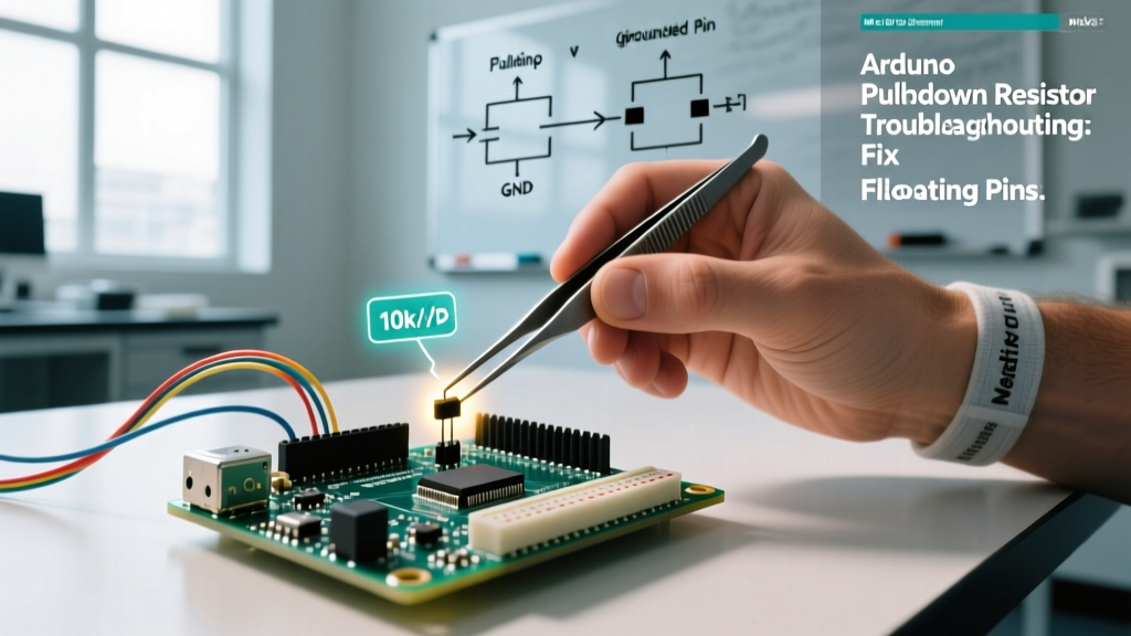
To fix this, we must provide a defined default state. A pulldown resistor ties the pin to GND through a specific resistance, ensuring it reads a stable LOW when the switch is open, while still allowing the pin to be pulled HIGH when the switch connects it to 5V.
CMOS Voltage Thresholds and the Danger Zone
To truly master Arduino pulldown resistor troubleshooting, you must look at the hardware datasheet. According to the Microchip ATmega328P datasheet, the microcontroller defines logic states based on specific voltage thresholds relative to VCC (which is 5V on a standard Uno):
- V_IL (Input Low Voltage): Maximum 0.3 × VCC (1.5V). Any voltage below 1.5V is guaranteed to be read as a LOW.
- V_IH (Input High Voltage): Minimum 0.6 × VCC (3.0V). Any voltage above 3.0V is guaranteed to be read as a HIGH.
The voltage range between 1.5V and 3.0V is the "undefined region." If EMI induces a voltage of 2.1V on a floating pin, the internal Schmitt trigger cannot decide if the pin is HIGH or LOW. This results in the ghost triggers and erratic behavior that plague beginner projects. A correctly sized pulldown resistor ensures the resting voltage is exactly 0V, safely below the 1.5V V_IL threshold.
Sizing Your Arduino Pulldown Resistor (With Calculation Table)
A common mistake is picking a random resistor from a kit without considering the electrical consequences. The standard value for an Arduino pulldown resistor is 10kΩ, but why? We must balance two competing factors: current draw and signal integrity.
When you press the button, current flows from the 5V rail, through the button, through the pulldown resistor, and into GND. Using Ohm's Law (I = V / R), a 10kΩ resistor draws 0.5mA (5V / 10,000Ω). This is a negligible amount of current, preserving battery life and keeping well within the ATmega328P's absolute maximum per-pin current limit of 40mA.
As detailed in SparkFun's guide on pull-up and pulldown resistors, choosing the wrong value can lead to hardware damage or persistent noise issues. Review the matrix below to select the correct component for your specific application:
| Resistor Value | Current Draw (at 5V) | Power Dissipation | Pros & Cons | Best Use Case |
|---|---|---|---|---|
| 1kΩ | 5.0 mA | 25 mW | Very strong pull, fast edges. Wastes power and generates unnecessary heat. | High-EMI industrial environments. |
| 10kΩ | 0.5 mA | 2.5 mW | The gold standard. Perfect balance of low power draw and noise immunity. | Standard breadboard prototyping & battery projects. |
| 100kΩ | 0.05 mA | 0.25 mW | Ultra-low power. Highly susceptible to EMI and parasitic capacitance. | Deep-sleep wearable sensors. |
| 1MΩ | 0.005 mA | 0.025 mW | Negligible current. Will likely fail due to PCB leakage currents and RF noise. | Not recommended for 5V Arduino GPIOs. |
The Internal Pulldown Myth: ATmega328P Hardware Limits
One of the most frequent troubleshooting dead-ends occurs when makers attempt to use software to fix a hardware problem. You may have seen code snippets utilizing pinMode(pin, INPUT_PULLUP) and assumed there is an equivalent INPUT_PULLDOWN command for the Arduino Uno.
Critical Hardware Limitation: The ATmega328P microcontroller features internal 20kΩ - 50kΩ pull-up resistors, but it does not possess internal pulldown resistors. If you are using an Arduino Uno, Nano, or Mega, you must wire a physical external resistor to GND. Attempting to configure a software pulldown on an AVR-based board will result in a compilation error or, worse, silent failure where the pin remains floating.
Note: If you have upgraded to a 32-bit architecture board like the Arduino Zero (SAMD21) or an ESP32, those specific silicon dies do include internal pulldown resistors, which can be activated via their respective core libraries. However, for standard 5V AVR boards, external hardware is mandatory.
Step-by-Step Troubleshooting Matrix
When your circuit misbehaves, use this diagnostic matrix to isolate the root cause. This aligns with the best practices outlined in the Arduino official digital pins documentation.
| Symptom | Root Cause | The Fix |
|---|---|---|
| Pin reads random HIGH/LOW when button is NOT pressed. | Floating pin. The input impedance is picking up ambient EMI. | Install a 10kΩ resistor between the GPIO pin and GND. Ensure the button connects the pin to 5V. |
| Pin is permanently stuck LOW, even when button is pressed. | Short circuit to GND, or the pulldown resistor value is too low (e.g., 10Ω), preventing the 5V rail from overcoming the ground path. | Check breadboard continuity. Replace the resistor with a verified 10kΩ component. Check for solder bridges. |
| Pin reads HIGH when pressed, but takes 2+ seconds to return to LOW. | Parasitic capacitance on long wire runs combined with a high-value resistor (e.g., 1MΩ) creating a slow RC discharge curve. | Decrease the pulldown resistor to 4.7kΩ or 1kΩ to discharge the parasitic capacitance faster. |
| Single button press registers as 3 or 4 rapid triggers in code. | Mechanical switch bounce. The physical metal contacts are vibrating upon impact. | This is not a pulldown failure. Implement software debouncing (e.g., a 50ms delay) or add a 100nF ceramic capacitor in parallel with the resistor. |
Advanced Fixes: Long Wires and High-EMI Environments
If you are building a permanent installation—such as a home automation wall switch or an automotive sensor rig—standard breadboard rules no longer apply. When you run wires longer than 2 meters (approx. 6.5 feet), the wire itself develops significant parasitic capacitance and acts as a massive antenna for RF interference.
The RC Time Constant Problem
Every wire has capacitance (C) and your pulldown resistor provides resistance (R). Together, they form an RC low-pass filter. The time constant (τ = R × C) dictates how fast the pin can return to 0V when the switch is released. If you use a 100kΩ pulldown resistor on a 5-meter shielded cable with 500pF of capacitance, the discharge time might be too slow for high-speed polling loops in your Arduino sketch.
The Fix: In long-wire scenarios, drop your Arduino pulldown resistor to 4.7kΩ or even 2.2kΩ. The slight increase in current draw (1mA to 2.2mA) is a worthy tradeoff for crisp, noise-free falling edges.
Adding Hardware Debouncing
If software debouncing is consuming too much CPU overhead or causing latency in your interrupt service routines (ISRs), you can fix switch bounce in the analog domain. Solder a 100nF (0.1µF) ceramic capacitor directly across the GPIO pin and GND, in parallel with your pulldown resistor. This creates a hardware low-pass filter that physically absorbs the micro-second voltage spikes caused by mechanical contact bounce, delivering a perfectly clean digital edge to the ATmega328P.
Summary Checklist for Stable Inputs
Before finalizing your schematic or soldering your perfboard, run through this final verification checklist:
- Verify the Chip: Confirm if your specific microcontroller (AVR vs. ARM/ESP) requires an external physical pulldown resistor.
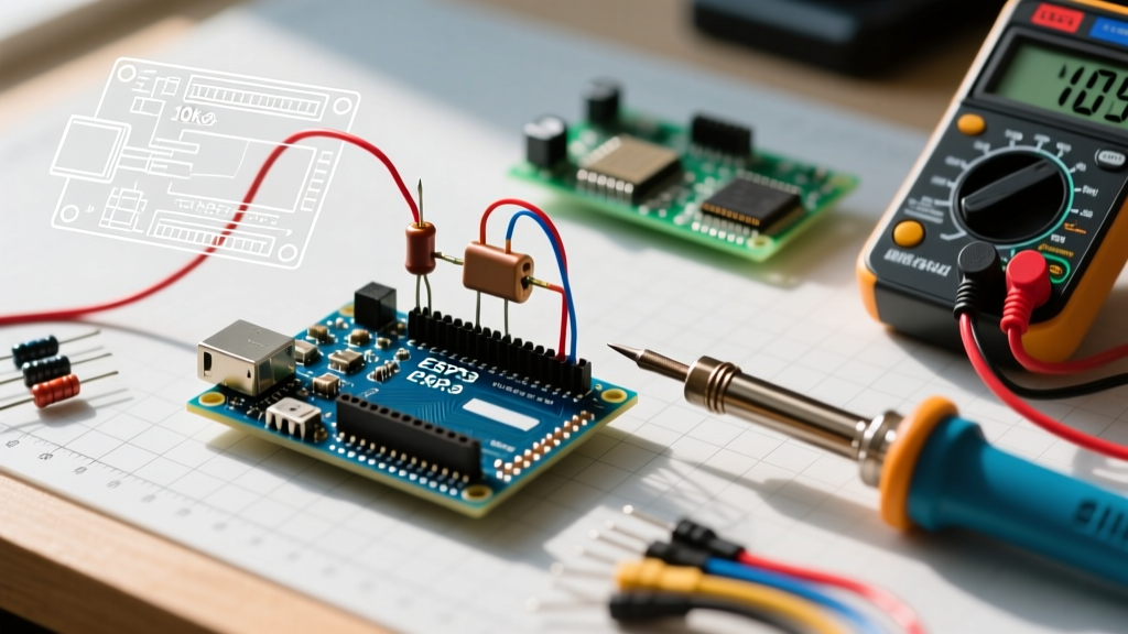
- Measure the Resistance: Use a multimeter to verify your resistor is actually 10kΩ (allowing for a 5% tolerance band).
- Check the Wiring Topology: Ensure the resistor connects directly from the GPIO pin to GND, and the switch bridges the GPIO pin to VCC (5V or 3.3V). Placing the resistor on the VCC side creates a pull-up, inverting your logic.
- Inspect for Flux Residue: If soldering, clean the board with isopropyl alcohol. Leftover acidic flux can create a high-resistance parasitic path to VCC, effectively fighting your pulldown resistor and causing ghost triggers.
By respecting the physics of CMOS inputs and properly sizing your components, you will entirely eliminate floating pin errors, resulting in robust, professional-grade Arduino projects.