
The Anatomy of the MPU-6050: Beyond the Breakout Board
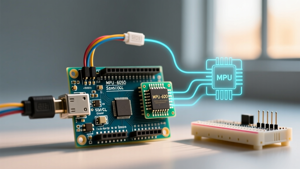
When makers and engineers discuss motion tracking, the MPU 6050 Arduino integration remains one of the most ubiquitous pairings in the DIY electronics space. Originally designed by InvenSense (now a TDK group company), the MPU-6050 is a 6-axis Inertial Measurement Unit (IMU) that combines a 3-axis MEMS accelerometer and a 3-axis MEMS gyroscope into a single silicon die. While newer 9-axis and 12-axis sensors like the ICM-42688-P have taken over commercial drones in 2026, the MPU-6050 persists as the undisputed king of educational robotics, balancing robots, and budget motion-capture gloves due to its massive legacy codebase and ultra-low cost.
Most hobbyists interact with this chip via the GY-521 breakout board. In the current market, genuine TDK InvenSense chips on hobbyist breakouts are rare; most $2.50 to $4.00 GY-521 modules utilize high-quality silicon clones. These clones generally replicate the I2C register map perfectly, though you may notice a slightly higher noise floor on the Z-axis gyroscope compared to premium $14.95 breakouts from brands like Adafruit or SparkFun, which feature onboard voltage regulation and Stemma QT/Qwiic connectors.
Sensor Fusion: Why Raw Data is Useless for Motion Tracking
To understand why a simple I2C read isn't enough, we must examine the physical limitations of MEMS sensors. If you attempt to build a self-balancing robot using only raw sensor data, your project will fail. Here is why:
- The Accelerometer: Measures proper acceleration (including gravity). It is excellent for finding the static 'down' vector, but it is incredibly noisy. Any high-frequency vibration from motors or wheels will corrupt the tilt angle calculation.
- The Gyroscope: Measures angular velocity (degrees per second). To get an angle, you must integrate this data over time. However, MEMS gyros suffer from bias instability and white noise. When integrated, this tiny noise accumulates, causing the calculated angle to 'drift' exponentially within seconds.
The solution is Sensor Fusion. By combining the high-frequency reliability of the gyroscope with the low-frequency stability of the accelerometer, you get a clean, drift-free angle. While you can write a Complementary Filter or a Madgwick AHRS (Attitude and Heading Reference System) algorithm in your Arduino sketch, doing so consumes valuable CPU cycles on an 8-bit ATmega328P. For a deep dive into the mathematics of these filters, the AHRS Madgwick Filter Documentation provides an excellent open-source breakdown of quaternion-based orientation estimation.
The Secret Weapon: The Digital Motion Processor (DMP)
The true genius of the MPU-6050 is not the MEMS sensors themselves, but the onboard Digital Motion Processor (DMP). The DMP is a proprietary, undocumented hardware co-processor embedded within the chip.
How the DMP Offloads the Arduino
Instead of forcing your Arduino to read raw X/Y/Z data at 200Hz and run complex trigonometric sensor fusion, you can upload a 3KB firmware blob to the DMP via I2C during the setup phase. Once running, the DMP handles the sensor fusion internally and pushes the results into the MPU-6050's 1024-byte FIFO (First-In-First-Out) buffer.
The output is not Euler angles (Pitch, Roll, Yaw), but Quaternions (w, x, y, z). Quaternions are a four-dimensional mathematical construct used to represent 3D rotations without suffering from Gimbal Lock—a catastrophic failure mode in Euler angles where two axes align and a degree of freedom is lost. Your Arduino only needs to wake up when an interrupt fires, read the quaternion from the FIFO buffer, and convert it to Euler angles for your motor controller.
I2C Wiring and Address Configuration
The MPU-6050 communicates exclusively via I2C. Proper hardware configuration is critical to prevent bus lockups. Below is the standard wiring matrix for an Arduino Uno or Nano.
| MPU-6050 Pin | Arduino Uno/Nano | Purpose & Notes |
|---|---|---|
| VCC | 3.3V (or 5V*) | Power supply. *See failure modes below regarding 5V tolerance. |
| GND | GND | Common ground reference. |
| SCL | A5 | I2C Clock line. Requires a 4.7kΩ pull-up resistor to VCC. |
| SDA | A4 | I2C Data line. Requires a 4.7kΩ pull-up resistor to VCC. |
| INT | D2 | Interrupt output. Connects to hardware INT0 for FIFO reading. |
| AD0 | GND or 3.3V | I2C Address selector. GND = 0x68, 3.3V = 0x69. |
For a comprehensive understanding of how the Arduino handles I2C communication at the register level, refer to the official Arduino Wire Library Reference.
Real-World Failure Modes and Hardware Edge Cases
When integrating the MPU 6050 Arduino setup into a physical prototype, theoretical wiring diagrams often fall short. Here are the most common edge cases and how to solve them:
1. The 'Magic Smoke' Voltage Tolerance Issue
The actual MPU-6050 silicon operates strictly at 3.3V. The chip has a separate VLOGIC pin for I2C bus voltage matching, but the main VCC pin powers the MEMS array and DMP. Many ultra-cheap GY-521 clone boards omit the onboard Low Dropout (LDO) voltage regulator to save $0.05 per unit. If you connect the VCC pin of these specific boards to the Arduino's 5V pin, you will instantly overvoltage and destroy the sensor. Actionable Fix: Always test continuity between VCC and the chip's VCC pad with a multimeter. If there is no LDO, you must wire VCC to the Arduino's 3.3V output.
2. I2C Bus Capacitance and Wire Length
I2C was designed for on-board communication, not long-distance wiring. If your MPU-6050 is mounted on a drone arm or a robotic limb more than 30cm away from the Arduino, the parasitic capacitance of the wires will degrade the square-wave clock signal, leading to corrupted I2C packets and random DMP crashes.
Pro-Tip: If you must run I2C lines over 30cm, use twisted-pair cables, drop the I2C bus speed from 400kHz to 100kHz using Wire.setClock(100000);, and upgrade your pull-up resistors from 4.7kΩ to 2.2kΩ to provide stronger drive current for the capacitive load.
3. The PWR_MGMT_1 Sleep Lock
Out of the factory, the MPU-6050 is in a low-power sleep mode. A common beginner mistake is attempting to read data immediately after powering the board, resulting in a stream of zeros. You must explicitly wake the chip by writing a 0x00 to the PWR_MGMT_1 register (Address 0x6B). Furthermore, to ensure the chip uses the primary internal oscillator rather than the less stable sleep-clock, it is best practice to write 0x01 to this register.
Software Stack: Why the Standard Wire Library Falls Short
While the built-in Arduino Wire.h library is sufficient for reading raw temperature or basic acceleration data, it is fundamentally inadequate for utilizing the DMP. The Wire.h library has a default 32-byte receive buffer. The DMP outputs a 28-byte quaternion packet, which fits, but if the FIFO buffer queues multiple packets before the Arduino reads them, the 32-byte limit causes buffer overflows and silent data truncation.
To properly interface with the DMP, the industry standard is the I2Cdevlib created by Jeff Rowberg. This library bypasses the standard Wire buffer limitations, handles the complex 3KB DMP firmware upload sequence, and manages the FIFO overflow interrupts automatically. When setting up your IDE, ensure you are using the latest fork of I2Cdevlib compatible with modern Arduino AVR and ESP32 cores, as legacy versions from 2016 often fail to compile under current GCC toolchains.
Summary: Raw vs. DMP Processing
To finalize your architectural decision, review the trade-offs between bypassing the DMP for raw data versus leveraging it for sensor fusion.
| Feature | Raw Data Mode (No DMP) | DMP Mode (Sensor Fusion) |
|---|---|---|
| MCU CPU Load | High (Requires software filtering) | Low (DMP handles math) |
| Output Format | Raw 16-bit integers (Accel/Gyro) | Quaternions (w, x, y, z) |
| Gimbal Lock | Prone (if using Euler math) | Immune (Quaternion based) |
| Setup Complexity | Low (Simple I2C reads) | High (Requires firmware upload) |
| Best Use Case | Simple step counters, shake detection | Drones, balancing robots, VR tracking |
Understanding the hardware nuances, I2C bus physics, and the mathematical advantages of the DMP will elevate your MPU 6050 Arduino projects from jittery prototypes to robust, commercial-grade motion tracking systems.
For further reading on the official hardware specifications and legacy documentation, you can review the TDK InvenSense MPU-6050 Product Overview.