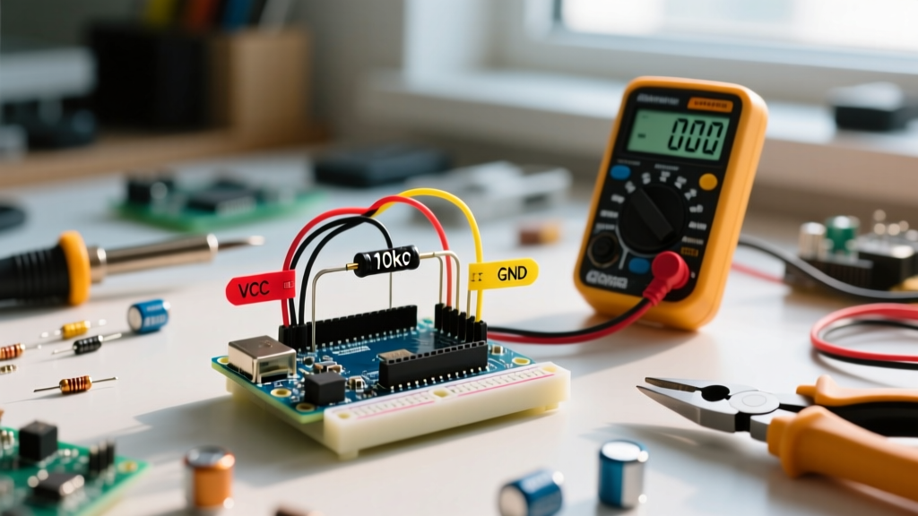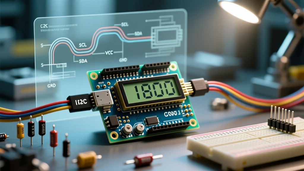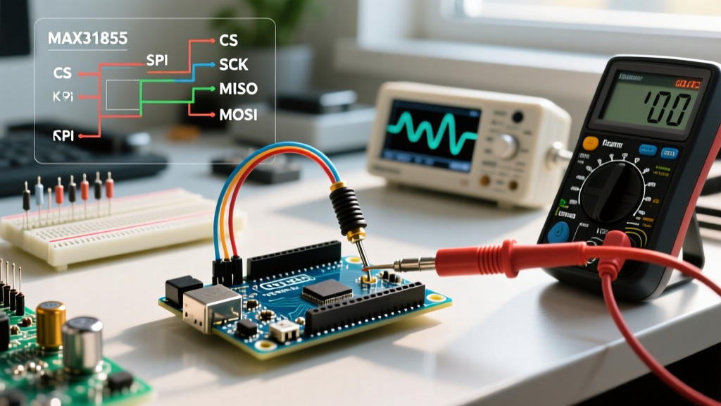

Setting up a high-temperature measurement system is a rite of passage for thermal engineering makers. However, when you attempt to make an Arduino read K type thermocouple data, you are frequently met with NaN (Not a Number) outputs, erratic 50°C jumps, or static temperature offsets. K-type probes generate microvolt-level signals that are highly susceptible to electromagnetic interference (EMI), ground loops, and logic-level mismatches.
In this error diagnosis guide, we will bypass generic wiring tutorials and dive deep into the hardware-level failure modes of the two most common amplifier ICs: the legacy MAX6675 and the modern, fault-detecting MAX31855. Whether you are using a classic 5V Arduino Uno R3 or a modern 3.3V Arduino Uno R4 Minima (retailing around $27.50 in 2026), understanding the physics and digital protocols behind these sensors is critical for stable data acquisition.
Decoding the 'NaN' Error: MAX31855 Fault Bit Diagnosis
The most common point of failure occurs when the serial monitor outputs NaN. If you are using the older MAX6675 chip, NaN simply means a communication timeout or a completely disconnected probe. However, the Analog Devices MAX31855 includes dedicated fault-detection bits in its 32-bit SPI data packet. When the Adafruit_MAX31855 library returns NaN, it is actively protecting you from invalid data by checking bits D0, D1, D2, and D16.
The Three Hardware Faults
- Open Circuit (OC - Bit D0): The thermocouple wires are broken, or the screw terminals are loose. The MAX31855 detects this by pulling the T+ and T- pins high internally; if the voltage doesn't change, the circuit is open.
- Short to GND (SCG - Bit D1): The thermocouple sheath or exposed wire is touching a grounded metal surface (like a kiln chassis or engine block). This creates a parallel resistance path that ruins the microvolt differential.
- Short to VCC (SCV - Bit D2): The probe is shorted to a positive voltage rail. This is common in DIY 3D printer hotends where the thermocouple wires melt and touch the 12V/24V heater cartridge wiring.
Diagnostic Action: Modify your C++ sketch to read the raw 32-bit integer via SPI before the library parses it. Use bitwise AND operations (data & 0x0001) to isolate the exact fault bit and print it to the serial monitor. This immediately tells you if the issue is a broken wire (OC) or an insulation failure (SCG/SCV).
Microvolt Vulnerability: Diagnosing EMI and Noisy Jumps
According to the NIST ITS-90 Thermocouple Database, a K-type thermocouple outputs approximately 41.276 µV per degree Celsius at room temperature. This incredibly weak signal means that a mere 1 mV of electromagnetic noise picked up by your wiring will translate to a massive 24°C error in your final reading.
Symptom: Erratic 10°C to 30°C Jumps
If your readings are stable at room temperature but jump wildly when a relay clicks, a stepper motor engages, or an AC compressor turns on, you are experiencing EMI coupling. The long thermocouple wires are acting as an antenna.
Hardware-Level Solutions for Signal Integrity
- Twisted Pair Routing: Never run K-type extension wire parallel to AC mains or stepper motor cables. Twist the thermocouple wires tightly (at least 10 twists per foot) to ensure induced noise affects both wires equally, allowing the MAX31855's differential amplifier to reject it as common-mode noise.
- RC Low-Pass Filtering: The Adafruit MAX31855 Breakout ($14.95) includes basic filtering, but in high-noise environments, you must add an external RC filter. Solder a 100nF ceramic capacitor and a 10µF tantalum capacitor in parallel directly across the T+ and T- screw terminals. This creates a hardware low-pass filter that shunts high-frequency EMI to ground before it reaches the IC's ADC.
- Grounding the Shield: If using a grounded metal-sheathed K-type probe (MgO insulated), ensure the sheath is grounded at one single point to the system earth. Grounding it at both the probe tip and the Arduino creates a ground loop, injecting 50/60Hz AC hum directly into your readings.
Cold Junction Compensation (CJC) Offset Errors
Symptom: Readings Offset by Exactly Room Temperature
You place your K-type probe in an ice bath (0°C), but your Arduino reads 22°C. Alternatively, the reading drifts upward by 5°C after the Arduino has been powered on for ten minutes.
The Root Cause: Thermocouples only measure the temperature difference between the hot tip and the cold junction (where the thermocouple wire meets the copper traces of the breakout board). The MAX31855 contains an internal diode to measure the PCB temperature (Cold Junction Compensation). If your breakout board is mounted directly next to the Arduino's 5V linear voltage regulator (which can easily reach 60°C under load), the IC assumes the cold junction is at 60°C and adds that to your final calculation.
The Fix: Thermally isolate the MAX31855 breakout board. Mount it away from the Arduino's power section, or use a 4-pin JST extension cable to move the amplifier board out of the enclosure's ambient heat zone. Never place the amplifier IC directly above a stepper motor driver or an AMS1117 LDO regulator.
5V vs 3.3V Logic Level SPI Clashes
A silent killer of MAX31855 modules is SPI logic level mismatch. The MAX31855 is a strictly 3.3V device. If you connect it directly to a 5V Arduino Uno R3, you are feeding 5V into the SCK (Clock) and CS (Chip Select) pins. While the MISO (Data Out) pin is safe because it only outputs 3.3V back to the Arduino, pushing 5V into the 3.3V input pins will eventually degrade the silicon, leading to intermittent read failures and corrupted SPI packets.
Diagnostic Checklist for SPI Logic
- Option A (Level Shifter): Use a BSS138 or CD4050 bidirectional logic level converter between the 5V Arduino and the 3.3V MAX31855. Cost: ~$1.50.
- Option B (Native 3.3V MCU): Migrate your project to a native 3.3V microcontroller. The ESP32-S3 or the Arduino Nano 33 BLE are ideal for thermocouple projects, eliminating the need for level shifters entirely while providing built-in Wi-Fi/Bluetooth for remote thermal monitoring.
- Option C (Voltage Divider): In a pinch, use a 2.2kΩ and 3.3kΩ resistor voltage divider on the SCK and CS lines to drop the 5V logic down to a safe 3.0V. Do not use this for high-speed SPI, but it works for the MAX31855's relatively slow 100kHz clock.
Diagnostic Troubleshooting Matrix
| Symptom | Probable Cause | Diagnostic Step | Solution |
|---|---|---|---|
Serial Monitor outputs NaN | Open Circuit or SPI Timeout | Read raw 32-bit hex via SPI; check Bit D0. | Tighten screw terminals; check for broken internal probe wire. |
| Reading is stuck at 0°C or 1024°C | MAX6675 CS pin floating | Verify CS pin goes LOW before reading. | Ensure CS is wired to a digital pin, not permanently grounded. |
| Wild jumps (±20°C) when relay clicks | EMI / Common-Mode Noise | Disconnect probe; short T+ and T- at the board. | Add 100nF/10µF RC filter; use twisted-pair extension wire. |
| Reading offset by +15°C to +30°C | CJC Thermal Coupling | Measure breakout board PCB temp with IR gun. | Move board away from Arduino LDO; use extension headers. |
| Intermittent SPI CRC / Read Errors | 5V Logic Overstress | Measure SCK/CS voltage with oscilloscope/multimeter. | Insert BSS138 level shifter or switch to 3.3V ESP32 MCU. |
Summary Checklist for Stable Reads
To ensure your Arduino read K type thermocouple implementation is bulletproof for industrial or high-stakes DIY applications, verify the following before deployment: Use the MAX31855 over the MAX6675 for fault detection and negative temperature support; implement a hardware RC filter at the screw terminals; physically separate the cold-junction PCB from heat-generating components; and respect the 3.3V logic limits of the SPI bus. By addressing the microvolt physics and digital protocol realities, you will eliminate ghost errors and achieve laboratory-grade thermal measurement accuracy.