
The Reality of Budget Maker Kits
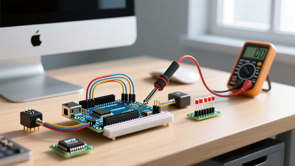
Unboxing a $35 to $45 Arduino starter kit—such as those from Elegoo, Rexqualis, or SunFounder—is a rite of passage for electronics hobbyists. These kits promise hundreds of Arduino kit components, from microcontrollers to sensors, all neatly organized in plastic tackle boxes. However, as any seasoned electrical engineer will tell you, the sheer volume of parts often masks significant quality control inconsistencies. Cloned microcontrollers, mislabeled transistors, and out-of-spec passive components are rampant in budget manufacturing.
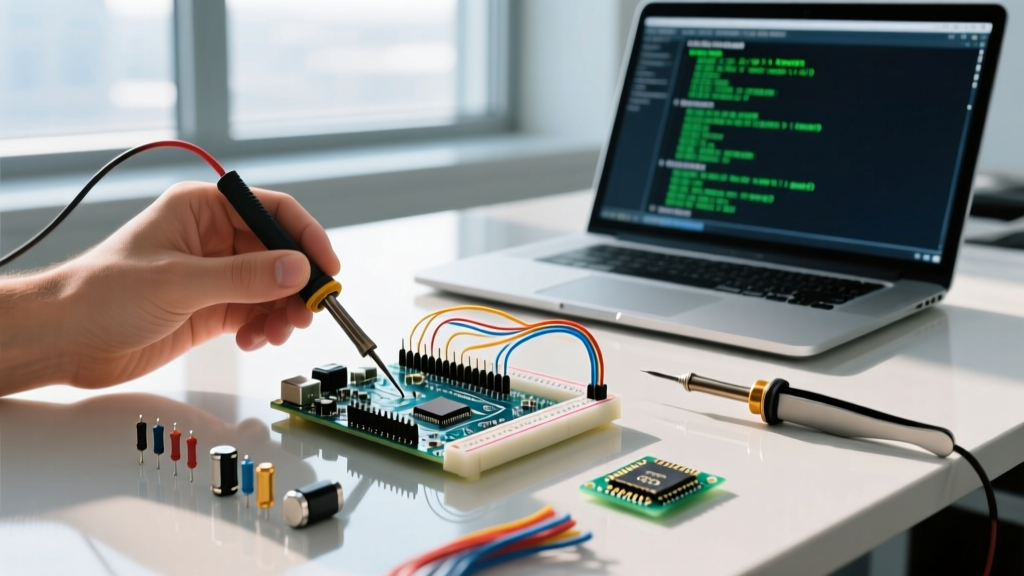
Before you wire up your first breadboard circuit, you must audit your inventory. This tutorial provides a step-by-step methodology to identify, test, and verify the most critical Arduino kit components using a standard Digital Multimeter (DMM) and visual inspection, ensuring your projects are built on a foundation of reliable hardware.
Phase 1: Inspecting the Microcontroller Board
The centerpiece of any kit is the Arduino Uno R3 compatible board. While the silkscreen may claim it is an authentic Uno, a quick visual inspection of the USB-to-Serial interface chip near the USB port will reveal its true lineage.
- Genuine Boards: Utilize the ATmega16U2 microcontroller for USB communication. This chip requires no special drivers on modern Windows 11 or macOS systems and supports advanced techniques like HID (Human Interface Device) emulation.
- Clone Boards: Typically use the CH340G or CP2102 USB-to-Serial chips to cut costs. While functionally identical for standard serial uploads, the CH340G requires you to manually download and install specific drivers from the manufacturer's repository before the IDE will recognize the COM port.
Pro Tip: If your clone board uses a CH340G chip and fails to upload sketches, verify your USB cable. Over 60% of upload failures in budget kits are caused by charge-only USB cables lacking the internal D+ and D- data wires. Always test with a verified data-sync cable.
Phase 2: Auditing Passive Components with a DMM
Passive components are the backbone of circuit protection and signal conditioning. Budget kits frequently source resistors and capacitors from surplus or low-tier manufacturing batches, leading to tolerance drift. According to SparkFun's comprehensive multimeter guide, verifying these values before deployment is critical for precision analog circuits.
Testing Resistors and Tolerance Drift
Most kits include 1/4W carbon film resistors with a stated tolerance of ±5%. Take the ubiquitous 220Ω resistor, commonly used as a current-limiting resistor for standard 5mm LEDs. Set your DMM to the lowest Ohms range (usually 200Ω or 2kΩ) and measure a sample of five resistors.
- Insert the resistor leads into the DMM probes.
- Read the value. A healthy 220Ω resistor should read between 209Ω and 231Ω.
- If you measure values outside this 5% window, or if the reading fluctuates wildly when you bend the lead, the component suffers from poor end-cap crimping. Bin these immediately to prevent LED burnout in parallel circuits.
The Potentiometer Wiper Test
Kits usually include 10kΩ single-turn cermet trimpots or rotary potentiometers. To test for "dead spots" or wiper noise:
- Set your DMM to continuity or resistance mode.
- Connect the black probe to Pin 1 (ground) and the red probe to Pin 2 (the wiper).
- Slowly rotate the shaft through its full 270-degree mechanical travel.
- The resistance should increase smoothly from 0Ω to 10kΩ. Any sudden drops to 0Ω or infinite spikes indicate a worn or oxidized carbon track, which will introduce severe noise if used in analog audio or sensor calibration circuits.
Phase 3: Verifying Active Components and ICs
Active components dictate the logic and power switching of your projects. Mislabeled parts are a notorious issue in generic kits, leading to frustrating debugging sessions.
Transistor Substitution: S8050 vs. 2N2222
Many kit inventories list the 2N2222 NPN transistor, a legendary component capable of switching up to 800mA. However, physical inspection often reveals the TO-92 package is actually stamped with S8050. The S8050 is a high-frequency, low-power NPN transistor with a maximum continuous collector current of just 500mA, and practically much less without a heatsink. If your circuit involves driving a small DC motor or a high-current relay coil, the S8050 will overheat and fail. Always read the physical stamping on the transistor casing, not just the kit's printed manifest.
The 555 Timer Discrepancy
The 555 timer IC is a staple in timing circuits. Kits may supply either the bipolar NE555P or the CMOS LMC555. As detailed in the Texas Instruments NE555 datasheet, the bipolar version can source and sink up to 200mA, allowing it to drive LEDs directly. The CMOS version, while drawing significantly less quiescent current, has a much lower output drive capability. Swapping them without adjusting your circuit's load expectations will result in dim outputs or failure to trigger.
Component Substitution and Failure Matrix
Use this reference table to cross-check the components in your kit against their expected specifications and common failure modes.
| Kit Component | Expected Specification | Common Kit Substitution | Edge Case / Failure Mode |
|---|---|---|---|
| NPN Transistor | 2N2222 (800mA Ic) | S8050 (500mA Ic) | Thermal runaway when driving relay coils > 70mA. |
| Voltage Regulator | L7805CV (1.5A Linear) | AMS1117-5.0 (1A LDO) | AMS1117 requires specific output capacitor ESR to prevent oscillation. |
| Electrolytic Capacitor | 100µF 16V (Radial) | 100µF 10V (Radial) | Dielectric breakdown if used on unregulated 12V DC barrel jack rails. |
| Optocoupler | PC817 (CTR 50-600%) | Generic EL817 | Lower Current Transfer Ratio requires higher LED drive current. |
Phase 4: Upgrading Sensors for Professional Results
While auditing your Arduino kit components, you must also evaluate their viability for modern, real-world applications. The most glaring example is the DHT11 temperature and humidity sensor included in almost every starter kit.
The DHT11 uses a basic thermistor and a resistive humidity measurement element. It offers a dismal 8-bit resolution, an accuracy of ±2°C, and requires a strict 1-second polling delay. For any 2026 IoT project requiring reliable environmental logging, the DHT11 is functionally obsolete.
The Upgrade Path: Replace the DHT11 with a Bosch BME280 breakout board (typically $10 to $14). The BME280 communicates via I2C or SPI, provides 20-bit resolution for temperature, and includes a barometric pressure sensor. When wiring the BME280 to your Arduino's 5V logic, ensure your breakout board includes onboard level shifters; otherwise, you must use a bidirectional logic level converter to step the SDA/SCL lines down to 3.3V to prevent frying the sensor's internal registers.
Troubleshooting Common Kit Infrastructure Failures
Beyond the electronic components themselves, the physical infrastructure provided in these kits—namely the breadboards and jumper wires—frequently causes phantom bugs. The Arduino Official Troubleshooting documentation frequently points to physical connection issues as the root cause of erratic serial outputs and sensor noise.
Breadboard Parasitic Capacitance and Contact Resistance
Budget solderless breadboards suffer from two primary issues:
- Contact Resistance: The internal metal leaf springs lose tension after a few insertions of 22 AWG solid core wire. This introduces a variable resistance (often 1Ω to 5Ω) at the node. In high-current paths, this causes voltage drops; in high-impedance analog sensor paths, it introduces thermal noise.
- Parasitic Capacitance: Adjacent rows in cheap breadboards exhibit high parasitic capacitance (up to 2-5 pF between adjacent strips). While irrelevant for blinking an LED at 1Hz, this capacitance will completely destroy the signal integrity of high-frequency I2C buses or SPI data lines running above 400kHz.
Actionable Fix: For any project involving I2C sensors (like the aforementioned BME280) or analog-to-digital conversion, keep your jumper wires under 10cm in length. If you experience intermittent I2C address failures, add external 4.7kΩ pull-up resistors directly to the SDA and SCL lines at the sensor end, bypassing the breadboard's internal trace capacitance.
Conclusion
Budget Arduino kits are an excellent entry point into embedded systems, but they require a critical eye. By taking an hour to audit your microcontroller's USB interface, test your passive components with a DMM, verify transistor part numbers, and plan strategic sensor upgrades, you transition from simply following tutorials to engineering robust, reliable hardware. Treat your component bin not as a guaranteed inventory, but as a raw material supply chain that requires rigorous quality assurance.