
The Anatomy of a Button Wiring Failure
Wiring a pushbutton to a microcontroller is universally considered a beginner milestone. Yet, when you actually attempt to figure out how to wire a button Arduino projects demand, the failure rate in early prototypes is surprisingly high. You upload your sketch, press the 6x6mm tactile switch, and the Serial Monitor either spits out ghost triggers, remains completely dead, or behaves erratically when you move your hand near the breadboard.
As of 2026, whether you are using a legacy ATmega328P-based Arduino Uno R3 or the newer Renesas RA4M1-powered Uno R4 Minima, the underlying physics of mechanical switches and CMOS GPIO (General Purpose Input/Output) pins remain unchanged. The errors rarely stem from the microcontroller itself; they stem from misunderstood electrical states, mechanical switch geometry, and parasitic breadboard capacitance.
This guide bypasses basic tutorials and approaches button wiring strictly from an Error Diagnosis perspective. We will dissect the three most common hardware and firmware faults and provide exact multimeter testing procedures to isolate them.
Diagnostic Matrix: Symptom to Root Cause
Before ripping apart your breadboard, cross-reference your exact symptom with this diagnostic matrix to identify the probable failure point.
| Observed Symptom | Probable Root Cause | Multimeter Test Procedure | Hardware / Firmware Fix |
|---|---|---|---|
| Pin reads random HIGH/LOW without pressing | Floating Input Pin (High Impedance) | Measure DC Voltage between Pin and GND while idle. Look for fluctuating mV readings. | Enable internal pull-up or add external 10kΩ resistor. |
| Registers 5-20 presses for a single physical click | Mechanical Contact Bounce | N/A (Requires Oscilloscope or software counter sketch to visualize) | Implement software debouncing (e.g., Bounce2 library) or hardware RC filter. |
| Pin always reads LOW (or HIGH), button does nothing | 90-Degree Tactile Switch Rotation Error | Set DMM to Continuity. Probe diagonal pins. Should be OPEN until pressed. | Rotate switch 90 degrees to bridge the correct internal terminals. |
| Intermittent connection when touching jumper wires | Breadboard Leaf Spring Fatigue / Oxidation | Measure resistance across jumper wire insertion points. Should be < 0.5Ω. | Replace breadboard or solder directly to perfboard. |
Error 1: The Floating Pin Phenomenon
The most frequent reason a button 'fails' is that the microcontroller pin is left in a high-impedance state when the button is open. CMOS inputs (like those on the Arduino's microcontrollers) have an incredibly high input impedance (often >100 MΩ). When the button is not pressed, the pin is essentially disconnected from both VCC and GND. It acts as an antenna, picking up electromagnetic interference (EMI) from your body, nearby AC mains wiring, or even the microcontroller's own clock oscillator.
Diagnosing and Fixing the Float
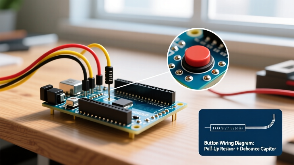
To fix this, the pin must be biased to a known voltage state when the button is open. According to the SparkFun guide on pull-up resistors, this is achieved using a pull-up or pull-down resistor.
- External Pull-Down: A 10kΩ resistor connects the pin to GND. The button connects the pin to 5V. Pin reads LOW normally, HIGH when pressed.
- Internal Pull-Up (Recommended): The microcontroller's internal resistor (typically 20kΩ to 50kΩ) connects the pin to VCC. The button connects the pin to GND. Pin reads HIGH normally, LOW when pressed.
Diagnostic Code Check: Ensure your setup function explicitly defines the pin mode. If you are relying on internal pull-ups, your code must read:
pinMode(2, INPUT_PULLUP);If you use INPUT instead of INPUT_PULLUP without an external resistor, you have identified your floating pin error. For deeper architecture specifics, consult the Arduino Digital Pins Documentation to verify the exact internal resistance values for your specific board variant.
Error 2: The 90-Degree Tactile Switch Trap
Standard through-hole tactile switches (like the ubiquitous 6x6x5mm Omron B3F series) have four pins. Beginners often assume these four pins represent four independent connection points. They do not.
The Internal Bridge Architecture
Inside the plastic housing, pins on the same side of the switch are permanently connected by a metal yoke. The switch only bridges the gap across the center divide when the plunger is depressed. If you insert the switch into a breadboard rotated 90 degrees from the correct orientation, you will permanently short your GPIO pin to either VCC or GND, or you will create an open circuit that the button can never close.
Expert Diagnostic Trick: Never trust the physical orientation of a tactile switch on a breadboard. Always take your digital multimeter (DMM), set it to the continuity/diode test mode, and probe two pins on the same side of the switch. If the DMM beeps continuously, those pins are internally bridged. Your wiring must cross the center gap of the switch to function correctly.
Error 3: Mechanical Contact Bounce
If your Serial Monitor shows a single button press registering as a dozen rapid triggers, you are not experiencing a wiring error; you are experiencing the physical reality of metallurgy. When the brass or phosphor-bronze contacts inside a tactile switch collide, they do not settle instantly. They physically bounce against each other for 1 to 5 milliseconds before making a solid connection. The Arduino's 16MHz (or 48MHz on the R4) processor executes millions of instructions per second, reading every single micro-bounce as a deliberate human press.
Implementing Robust Software Debouncing
While hardware debouncing using an RC (Resistor-Capacitor) low-pass filter paired with a 74HC14 Schmitt Trigger inverter is electrically elegant, it wastes breadboard space and adds component costs. In 2026, software debouncing is the industry standard for maker projects.
The Bounce2 library remains the most robust, non-blocking solution for the Arduino ecosystem. Unlike the basic delay(50) method—which halts your entire microcontroller and ruins real-time sensor polling—Bounce2 uses state-change timing.
Bounce2 Diagnostic Implementation
#include <Bounce2.h>

Bounce debouncer = Bounce();
const int BUTTON_PIN = 2;

void setup() {
  Serial.begin(115200);
  pinMode(BUTTON_PIN, INPUT_PULLUP);
  debouncer.attach(BUTTON_PIN);
  debouncer.interval(25); // 25ms debounce window
}

void loop() {
  debouncer.update();
  if (debouncer.fell()) {
    Serial.println('Button Pressed (Validated)');
  }
}
Tuning the Interval: Standard 6x6mm tactile switches usually exhibit 2ms to 5ms of bounce. Setting the interval() to 10ms is generally safe. If you are using larger, industrial panel-mount momentary switches (like the Schneider XB4 series), contact bounce can exceed 20ms, requiring you to increase the interval to 50ms to prevent ghost triggers.
Hardware Environment: Breadboard Parasitics and Fatigue
If your code is flawless and your switch orientation is correct, but the circuit still fails intermittently when you tap the desk, your prototyping environment is the culprit. Solderless breadboards rely on nickel-silver leaf springs to grip jumper wires. Cheap, mass-produced breadboards (often bundled in sub-$15 starter kits) suffer from rapid oxidation and spring fatigue.
When a leaf spring loses tension, the contact resistance between the wire and the bus strip jumps from <0.1Ω to over 50Ω. In a 5V logic circuit pulling minimal current, this might not drop the voltage below the ATmega328P's logical LOW threshold (1.5V). However, it creates an unstable node highly susceptible to EMI, effectively recreating the floating pin error described earlier.
The Diagnostic Workflow for Intermittent Hardware
- The Wiggle Test: Run a continuous loop printing the pin state. Gently wiggle the jumper wires at the breadboard insertion point. If the state flips, the leaf spring is fatigued.
- Bus Strip Continuity: Use a DMM to measure resistance across the power rails. A healthy breadboard will read near 0.0Ω across a 30-hole span. If you read >2Ω, the internal metal strips are oxidized or fractured.
- The Bypass: Solder the tactile switch and a 10kΩ pull-down resistor directly to a piece of perfboard or use a high-quality prototyping board like the BusBoard BB830 (typically priced around $8.50) to rule out environmental faults.
Summary: A Systematic Approach to Button Wiring
Understanding how to wire a button Arduino setups require goes far beyond connecting Pin A to Pin B. It requires managing high-impedance states with pull-up resistors, respecting the internal geometry of 4-pin tactile switches, and filtering mechanical contact bounce in firmware. By applying the diagnostic matrix and multimeter tests outlined above, you can isolate and resolve 99% of pushbutton input failures in under five minutes, ensuring your microcontroller reads human intent exactly as it was designed to.