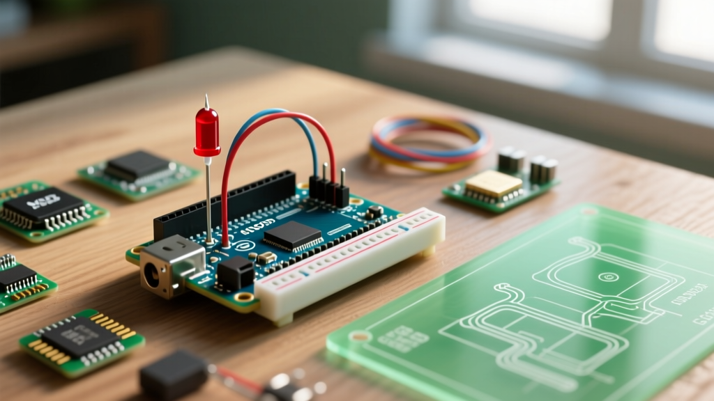

Learning how to control LEDs with Arduino is the foundational rite of passage for every embedded systems engineer and maker. However, moving beyond the basic 'Blink' sketch requires a solid grasp of hardware limits, Ohm’s law, and pulse-width modulation (PWM). This quick reference guide and FAQ cuts through the fluff, providing exact component values, wiring topologies, and troubleshooting frameworks for modern boards like the Arduino Uno R4 Minima and classic Nano clones.
Quick Reference: Standard 5mm LED Resistor Values
When driving standard 5mm through-hole LEDs directly from a 5V Arduino digital pin, you must use a current-limiting resistor. The formula is R = (Vs - Vf) / If, where Vs is the source voltage (5V), Vf is the LED forward voltage, and If is the target forward current (typically 20mA). Below are the exact resistor values you should keep in your bench kit.
| LED Color | Typical Vf (Volts) | Target Current | Calculated Resistor | Standard E12 Value to Use |
|---|---|---|---|---|
| Red | 2.0V | 20mA | 150Ω | 180Ω or 220Ω |
| Yellow / Green | 2.1V | 20mA | 145Ω | 150Ω or 180Ω |
| Blue / White | 3.2V | 20mA | 90Ω | 100Ω or 120Ω |
| UV (Ultraviolet) | 3.3V | 20mA | 85Ω | 100Ω |
Note: Always round up to the nearest standard E12/E24 resistor value to ensure the LED is slightly underdriven, which dramatically extends its lifespan and reduces thermal output.
Hardware & Wiring FAQs
Do I absolutely need a current-limiting resistor?
Yes. A common beginner misconception is that the internal resistance of the Arduino’s microcontroller is enough to limit current. It is not. LEDs have a highly non-linear I-V curve; once the forward voltage threshold is crossed, their resistance drops to near zero, causing a thermal runaway effect. Without a resistor, the LED will attempt to draw infinite current, limited only by the microcontroller’s pin. This will either destroy the LED instantly or fry the ATmega328P/RA4M1 pin output transistor. For a comprehensive overview of pin architecture, refer to the Arduino Digital Pins Foundation guide.
What is the maximum current an Arduino pin can supply?
For the classic ATmega328P (Uno R3, Nano) and the Renesas RA4M1 (Uno R4 Minima), the recommended continuous current per I/O pin is 20mA. The absolute maximum rating is 40mA, but operating at this limit causes excessive voltage droop and silicon degradation. Furthermore, there is a total package current limit (usually 200mA for the ATmega328P across all VCC/GND pins combined). If you need to drive 15 LEDs at 20mA each (300mA total), you cannot wire them directly to the GPIO pins; you must use external drivers.
How do I wire high-power 1W or 3W Star LEDs?
High-power LEDs (like the Cree XLamp series) draw 350mA to 700mA and require heat sinking. You cannot drive these directly. You must use a logic-level N-channel MOSFET. Critical Component Choice: Do not use the IRF520 module commonly sold in beginner kits. The IRF520 requires 10V at the gate to fully open (low Rds(on)). At the Arduino’s 5V logic level, it will only partially conduct, overheat, and drop voltage. Instead, use a true logic-level MOSFET like the IRLZ44N (Vgs(th) of 1V-2V, fully enhanced at 5V). Wiring topology:
- Gate: Connect to Arduino PWM pin via a 100Ω gate resistor (prevents high-frequency ringing).
- Source: Connect directly to Arduino GND.
- Drain: Connect to the LED Cathode (negative).
- LED Anode: Connect to an external constant-current LED driver or a 12V power supply via an appropriate current-limiting power resistor.
Code, PWM, and Fading FAQs
Which pins support PWM fading on modern boards?
Pulse Width Modulation (PWM) simulates analog voltage by rapidly toggling the pin HIGH and LOW. On the classic Uno R3, PWM pins are marked with a tilde (~) and include pins 3, 5, 6, 9, 10, and 11. If you are using the Arduino Uno R4 Minima (retailing around $27.50 in 2026), the RA4M1 chip offers vastly superior PWM capabilities. Almost all digital pins support 8-bit, 10-bit, or 12-bit PWM resolution. To utilize 12-bit resolution (0-4095) for ultra-smooth LED fading, you must configure the PWM resolution in your setup block:
void setup() {
  // Set PWM resolution to 12 bits on Uno R4
  analogWriteResolution(12);
  pinMode(9, OUTPUT);
}

void loop() {
  // Fades smoothly using 12-bit range (0 to 4095)
  for(int i = 0; i < 4096; i++) {
    analogWrite(9, i);
    delay(2);
  }
}
For standard 8-bit fading (0-255), consult the official Arduino Fade tutorial.
Why does my LED flicker on camera when using PWM?
Standard Arduino PWM operates at a default frequency of roughly 490 Hz (or 980 Hz on pins 5 and 6). While this is too fast for the human eye to perceive, digital camera sensors (especially smartphones with rolling shutters) will capture this as severe flickering or banding.
The Fix: If you are building a project for video production or photography, you must increase the PWM frequency above 1kHz (ideally 20kHz+). On AVR boards, this requires manipulating Timer1 registers directly. On ARM-based boards like the Uno R4 or Teensy, you can use the analogWriteFrequency(pin, frequency) function to push the switching rate beyond camera detection thresholds.
Troubleshooting Common Failures
The Arduino resets or disconnects when I turn on multiple LEDs
Failure Mode: You upload a sketch that turns on 8 LEDs simultaneously. The Arduino’s onboard voltage regulator overheats, or the USB port triggers an over-current protection shutoff, causing the microcontroller to brownout and reset. Diagnosis: Standard PC USB 2.0 ports are limited to 500mA. If your 8 LEDs draw 20mA each (160mA), and the microcontroller draws 50mA, you are at 210mA. This seems safe, but cheap USB cables with high AWG (thin wires) cause severe voltage droop. If the voltage at the Arduino’s 5V rail drops below 4.5V, the brownout detector (BOD) will trigger a reset. Solution: Never power more than 4-5 standard LEDs directly from USB. For larger arrays, bypass the onboard 5V regulator and inject power directly into the 5V pin using a dedicated 5V 2A (or higher) buck converter or wall adapter. For deep dives into LED power management, the SparkFun LED Tutorial offers excellent hardware safety guidelines.
My LED is glowing faintly even when the pin is set to LOW
Failure Mode: Ghosting or faint illumination when the GPIO pin is outputting 0V.
Diagnosis: This usually occurs when using long, unshielded jumper wires in a breadboard environment, creating parasitic capacitance, or when the pin is accidentally configured as INPUT instead of OUTPUT (floating pin). Another common cause is a damaged microcontroller pin where the internal pull-down transistor has been compromised by a previous short circuit.
Solution: Verify your pinMode() declarations. If the pin is confirmed as an OUTPUT and the issue persists, add a 10kΩ pull-down resistor between the GPIO pin and GND to bleed off any parasitic charge.
Advanced Quick Reference: Direct Drive vs. LED Drivers
As your projects scale from a single indicator LED to multi-channel lighting arrays, you must choose the correct driving topology. Refer to the Texas Instruments TLC5940 Datasheet for professional constant-current driver specifications.
| Driving Method | Max Current per Channel | Best Use Case | Approx. Component Cost (2026) |
|---|---|---|---|
| Direct GPIO Pin | 20mA (40mA peak) | Status indicators, single 5mm LEDs | $0.00 (Built-in) |
| BJT Transistor (2N2222) | 600mA | Low-cost switching for LED strips (requires base resistor) | $0.05 per unit |
| Logic MOSFET (IRLZ44N) | 47A (Thermal limited) | High-power 1W/3W Star LEDs, long 12V LED strips | $0.60 per unit |
| Constant Current IC (TLC5940) | 120mA (per channel, 16ch) | RGB LED matrices, precise color mixing, POV displays | $2.50 per IC |
By mastering these hardware limits, selecting the correct logic-level components, and utilizing the appropriate PWM resolutions, you can reliably control any LED configuration with your Arduino ecosystem.