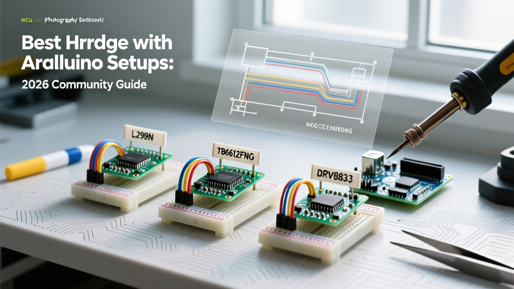

The Evolution of Motor Control: Why Your H-Bridge Choice Matters in 2026
If you have spent any time on maker forums or GitHub repositories over the last few years, you already know that the classic L293D motor shield is practically a relic. When building an h bridge with arduino microcontrollers today, the community has largely pivoted toward modern MOSFET-based drivers that offer higher efficiency, lower heat dissipation, and better logic-level compatibility. Whether you are building a line-following robot, an automated rover, or a motorized camera slider, selecting the right motor driver IC is the difference between a project that works on the bench and one that survives in the real world.
In this 2026 community resource roundup, we are synthesizing the best hardware recommendations, wiring topologies, and software tricks shared by veteran electrical engineers and robotics hobbyists. We will cut through the outdated tutorials and focus on actionable, high-E-E-A-T data to get your motors spinning efficiently.
Community Top Picks: Comparing the Best H-Bridge ICs
Not all H-bridges are created equal. The internal architecture (BJT vs. MOSFET) dictates your voltage drop, thermal performance, and battery life. Below is the consensus comparison matrix based on current community benchmarks and 2026 market pricing.
| Driver IC / Module | Architecture | Continuous Current | Voltage Drop | Logic Levels | Avg. Price (2026) | Best Use Case |
|---|---|---|---|---|---|---|
| L298N | BJT Darlington | 2.0A per channel | ~2.0V - 3.0V | 5V only | $3.00 - $5.00 | Beginner kits, high-voltage (12V+) heavy motors |
| TB6612FNG | MOSFET | 1.2A (3.2A peak) | ~0.5V | 2.7V - 5.5V | $5.00 - $8.00 | 3.3V MCUs (ESP32), battery-powered rovers |
| DRV8833 | MOSFET | 1.5A (2.0A peak) | ~0.6V | 2.7V - 5.5V | $4.00 - $6.00 | Compact builds, built-in overcurrent protection |
| BTS7960 | High-Power MOSFET | 43A (theoretical) | ~0.1V | 5.5V logic opto-isolated | $12.00 - $18.00 | E-bikes, heavy-duty actuators, 12V-24V systems |
Community Warning on the L298N: The L298N uses bipolar junction transistors (BJTs) in a Darlington pair configuration. This results in a massive voltage drop. If you supply 6V to the VCC pin to run a 6V motor, the motor will only see about 3.5V to 4V. For low-voltage battery projects, the community universally recommends the TB6612FNG breakout boards to preserve battery voltage and extend runtimes.
Wiring & Decoupling: The "Secret Sauce" from the Forums
The number one reason an h bridge with arduino setup fails—or causes the microcontroller to randomly reset—is poor power decoupling and ground routing. Motors are highly inductive loads; when they start, they draw massive stall currents, and when they stop, they generate back-EMF voltage spikes.
The Golden Rule of Decoupling Capacitors
Veteran forum members insist on a two-tier capacitor strategy for every motor driver board:
- High-Frequency Noise Suppression: Solder a 100nF (0.1µF) MLCC ceramic capacitor directly across the two terminals of the DC motor. This suppresses the high-frequency brush noise that can interfere with the Arduino's ADC readings and I2C communication lines.
- Bulk Energy Storage: Place a 100µF to 470µF electrolytic capacitor across the main power supply rails (VCC and GND) as close to the H-bridge IC's power pins as possible. This acts as a local energy reservoir to handle the sudden current spikes during motor startup, preventing voltage brownouts.
Grounding Topology: Avoiding the Reset Loop
If your Arduino resets the moment the motor spins, you likely have a ground loop or a shared USB power bottleneck. You must tie the Arduino GND, the Motor Power Supply GND, and the H-Bridge Logic GND together. The community prefers a star grounding topology, where all ground wires meet at a single, thick terminal block or copper pour, rather than daisy-chaining grounds from the Arduino to the driver and then to the battery.
Software & Libraries: Pushing Beyond analogWrite()
While the standard Arduino analogWrite() function is fine for blinking LEDs, it is often suboptimal for motor control. The default PWM frequency on most Arduino Uno pins is roughly 490Hz (with pins 5 and 6 at 980Hz). This low frequency falls squarely within the human hearing range, resulting in an annoying, high-pitched whine from the motor coils.
Shifting PWM to Ultrasonic Frequencies
To eliminate motor whine, the community recommends altering the hardware timers to push the PWM frequency above 20kHz. By manipulating the Timer1 registers on an ATmega328P (pins 9 and 10), you can achieve a silent 31.25kHz PWM signal.
Add this to your setup() function:
TCCR1B = TCCR1B & B11111000 | B00000001; // Set Timer1 to 31.25kHz
Edge Case Warning: Changing Timer1 will break the Servo.h library, as it relies on Timer1 for its 50Hz pulse generation. If you need both silent motors and servos, use the PWM.h library to manipulate Timer2 instead, or switch to a 32-bit ARM board like the Arduino Nano 33 IoT where timer conflicts are easily managed via hardware PWM channels.
Troubleshooting Edge Cases: Logic Levels and Thermal Shutdown
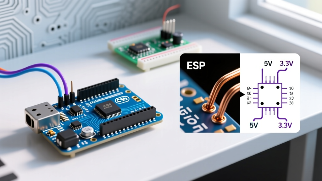
When integrating an h bridge with arduino boards, or more modern 3.3V alternatives like the ESP32 or Arduino Nano RP2040 Connect, logic level mismatches cause silent failures.
- The 3.3V Logic Problem: The classic L298N requires a minimum of 2.3V for a logical HIGH, but its onboard 5V regulator and optocouplers (on some clone boards) often demand a solid 5V to trigger reliably. If you are using a 3.3V MCU, feed the L298N logic pins through a bidirectional logic level shifter, or bypass the L298N entirely in favor of the TI DRV8833, which natively accepts 2.7V logic thresholds.
- Thermal Shutdown (OCP): Modern drivers like the DRV8833 and TB6612FNG feature Over-Current Protection (OCP) and thermal shutdown. If your motor stalls, the driver will silently cut power to save itself. The Arduino will still output PWM, but the motor won't move. Always implement a current-sensing resistor (shunt) and read it via an analog pin to detect stalls programmatically before the IC thermal-locks.
Frequently Asked Questions (FAQ)
Can I power the Arduino and the H-bridge from the same battery pack?
Yes, but with strict caveats. If you are using a 2S LiPo (7.4V) or a 4x AA holder (6V), you can feed the motor driver's VCC directly. However, do not use the L298N's onboard 5V linear regulator to power your Arduino if you are drawing more than 200mA from the motors. The linear regulator will overheat and cause the Arduino to brownout. Use a dedicated buck converter (like the LM2596 module) to step down the battery voltage to a clean 5V for the microcontroller.
Why are Schottky diodes recommended over standard 1N4007 flyback diodes?
Standard 1N4007 rectifier diodes have a slow reverse recovery time. When PWM switching at 20kHz, the diode doesn't have time to recover before the next pulse, leading to massive heat generation and voltage spikes. Schottky diodes (like the 1N5819) have near-instantaneous recovery times and a lower forward voltage drop (0.4V vs 0.7V), making them vastly superior for high-frequency H-bridge flyback protection.
Is the BTS7960 43A module actually capable of 43 Amps?
The community consensus is a hard "no." While the Infineon BTS7960 IC datasheet theoretically lists high current capabilities under perfect, infinite-heatsink conditions, the cheap red PCB modules sold online feature undersized copper traces and poor thermal vias. In real-world 2026 testing, these modules safely handle about 15A to 20A continuous before the PCB traces begin to delaminate or the IC overheats. For true 40A+ applications, build a custom PCB with 2oz copper or use automotive-grade solenoid contactors.