
The Foundation of Microcontroller Programming
In the maker community, the blink Arduino sketch is universally recognized as the "Hello World" of embedded systems. While it seems trivial, successfully blinking an LED validates your toolchain, confirms your board's microcontroller is responsive, and introduces the fundamental execution loop of C++ in the Arduino IDE. Whether you are using a legacy Arduino Uno R3 or the modern Arduino Uno R4 Minima, mastering this basic I/O operation is the critical first step before tackling complex sensor arrays or motor control.
This comprehensive guide moves beyond the basic copy-paste tutorial. We will cover precise hardware requirements, external breadboard wiring with Ohm's Law calculations, non-blocking code architecture using millis(), and high-power load switching.
Hardware Requirements & 2026 Market Pricing
Before writing code, ensure your workbench is equipped with the correct components. While the classic ATmega328P-based boards are still prevalent, the Renesas RA4M1-based R4 series has become the standard for new projects in 2026 due to its 48MHz clock speed and native DAC.
| Component | Recommended Model | Avg. Price (2026) | Purpose |
|---|---|---|---|
| Microcontroller Board | Arduino Uno R4 Minima | $19.50 | Main logic and GPIO control |
| Standard LED | 5mm Diffused Red (2.0Vf) | $0.10 | Visual output indicator |
| Current Limiting Resistor | 220Ω 1/4W Carbon Film | $0.02 | Prevents LED burnout and GPIO damage |
| Prototyping Base | 400-Tie-Point Breadboard | $5.00 | Solderless circuit assembly |
| Wiring | 22 AWG Solid Core Jumper Kit | $8.00 | Breadboard connections |
Anatomy of the Basic Blink Arduino Sketch
The default Blink sketch relies on two primary functions: setup() and loop(). The setup() function runs exactly once upon power-up or reset, configuring the hardware. The loop() function runs continuously, executing your main logic.
void setup() {
  // Initialize digital pin 13 as an output.
  pinMode(13, OUTPUT);
}

void loop() {
  digitalWrite(13, HIGH);  // Turn the LED on (HIGH is the voltage level)
  delay(1000);             // Wait for 1000 milliseconds (1 second)
  digitalWrite(13, LOW);   // Turn the LED off by making the voltage LOW
  delay(1000);             // Wait for a second
}
The pinMode() function configures the internal multiplexer of the microcontroller to route the pin to the output driver circuit rather than the input buffer. Pin 13 is historically tied to the onboard SCK LED, making it the default choice for quick diagnostics.
External Wiring: Calculating the Correct Resistor
Relying solely on the onboard LED limits your physical design. Wiring an external LED to a breadboard requires a current-limiting resistor to prevent the LED from drawing excessive current, which can destroy both the LED and the microcontroller's GPIO pin.
The Ohm's Law Calculation
Never wire an LED directly to a 5V or 3.3V logic pin. You must calculate the resistor value based on the LED's Forward Voltage (Vf) and desired Forward Current (If).
Formula: R = (V_source - V_LED) / I_LED
Example for a Standard Red LED:
V_source = 5.0V (Arduino Uno logic high)
V_LED = 2.0V (Typical forward voltage for red)
I_LED = 0.015A (15mA, a safe continuous current)
R = (5.0 - 2.0) / 0.015 = 3.0 / 0.015 = 200 Ohms
Since 200Ω is not a standard E12 resistor value, we round up to the nearest standard value: 220Ω.
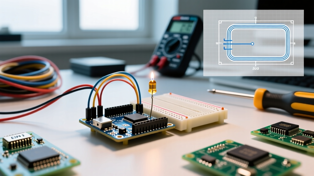
Step-by-Step Breadboard Assembly
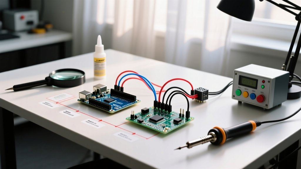
- Insert the 220Ω resistor into the breadboard. Connect one leg to Arduino Pin 8 (we use 8 to demonstrate custom pin mapping) and the other leg to an empty tie-point row.
- Insert the Anode (long leg) of the 5mm LED into the same row as the resistor.
- Insert the Cathode (short leg, flat edge) of the LED into the breadboard's ground rail.
- Run a jumper wire from the Arduino's GND pin to the breadboard's ground rail.
Leveling Up: Non-Blocking Code with millis()
The basic sketch uses delay(), which is a blocking function. When the microcontroller executes delay(1000), it sits idle. It cannot read sensors, process serial data, or update displays. For any real-world project, you must use the millis() function to track time without halting the CPU.
const int ledPin = 8;
int ledState = LOW;
unsigned long previousMillis = 0;
const long interval = 1000; // Interval in milliseconds

void setup() {
  pinMode(ledPin, OUTPUT);
}

void loop() {
  unsigned long currentMillis = millis();

  // Check if the interval has passed
  if (currentMillis - previousMillis >= interval) {
    // Save the last time you blinked the LED
    previousMillis = currentMillis;

    // Toggle the LED state
    ledState = (ledState == LOW) ? HIGH : LOW;
    digitalWrite(ledPin, ledState);
  }

  // You can add other non-blocking tasks here
  // e.g., readSensors(); updateDisplay();
}
This state-machine approach allows the Arduino to blink the LED exactly every 1000ms while dedicating the remaining 99% of the CPU cycles to other tasks in the loop().
Troubleshooting Matrix: Common Failure Modes
Even a simple blink Arduino circuit can fail. Use this diagnostic matrix to isolate hardware and software faults.
| Symptom | Probable Cause | Actionable Fix |
|---|---|---|
| LED is completely dark | Reversed polarity or dead GPIO pin | Swap LED legs. Verify Anode (long) faces the resistor. Test pin with a multimeter in DC Voltage mode during HIGH state. |
| LED stays solid ON | Missing pinMode or floating pin |
Ensure pinMode(pin, OUTPUT) is in setup(). Unconfigured pins default to high-impedance inputs and can float HIGH. |
| LED flickers rapidly | Missing delay() or logic error |
If using delay(), ensure both HIGH and LOW states have delays. If using millis(), check that previousMillis is actually updating inside the if block. |
| Upload fails (avrdude error) | Wrong COM port or bootloader issue | Check Tools > Port. If using a clone board, install the CH340 USB-Serial driver. Press the physical RESET button right as "Uploading..." appears. |
| LED glows dimly | Resistor value too high or insufficient current | Verify resistor bands. A 10kΩ resistor will limit current to <1mA, resulting in a faint glow. Replace with 220Ω. |
Advanced Edge Case: Driving High-Power Loads
A common beginner mistake is attempting to use the digitalWrite() function to directly switch high-power loads like 12V LED strips, automotive relays, or DC motors. Do not do this.
The ATmega328P (Uno R3) has an absolute maximum DC current limit of 40mA per I/O pin, and a total package limit of 200mA. The Renesas RA4M1 (Uno R4) allows slightly higher per-pin sourcing but still enforces strict package-level thermal limits. Exceeding these limits will permanently silicon-fry the internal output driver transistors.
The MOSFET Solution
To blink a 12V, 2A LED strip, use a logic-level N-Channel MOSFET like the IRLZ44N.
- Gate (G): Connect to Arduino Pin 8 via a 150Ω gate resistor (prevents high-frequency ringing).
- Drain (D): Connect to the negative terminal of your 12V load.
- Source (S): Connect to the shared Ground (Arduino GND and 12V Power Supply GND must be tied together).
- Pull-down Resistor: Add a 10kΩ resistor between the Gate and Ground to ensure the MOSFET stays off during Arduino boot-up when pins are floating.
By using the MOSFET as a voltage-controlled switch, your Arduino only supplies a few microamps to the Gate, safely isolating the low-voltage logic from the high-current load while still allowing you to use the exact same blink Arduino code structures outlined above.