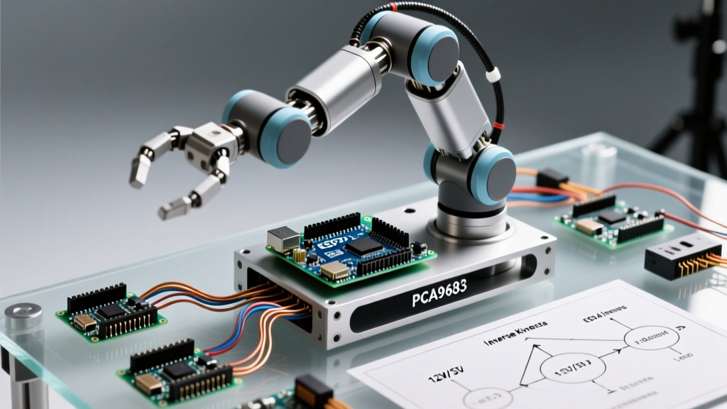

The Core Concept: Why Arduino for Robotic Arms?
Designing a robotic arm Arduino project requires bridging the gap between software logic and high-torque physical actuation. While industrial arms rely on PLCs and dedicated motion controllers, the Arduino ecosystem offers an accessible, highly customizable foundation for 4-DOF (Degrees of Freedom) to 6-DOF desktop manipulators. However, treating an Arduino simply as a pin-toggling microcontroller is a recipe for jittery motion and brownout resets. A successful build demands a systems-engineering approach encompassing floating-point kinematics, I2C bus management, and high-current power distribution.
Hardware Architecture: MCU Selection Matrix
The choice of microcontroller dictates your arm's computational ceiling, specifically regarding Inverse Kinematics (IK) calculations. While the Arduino Uno is ubiquitous, its 8-bit ATmega328P architecture struggles with the floating-point math required for real-time spatial coordinate translation.
| MCU Board | Architecture | IK Math Performance | I/O & Connectivity | Best Use Case |
|---|---|---|---|---|
| Arduino Uno R3 | 8-bit AVR (16MHz) | Poor (Software FPU emulation causes lag) | 14 Digital, 6 Analog | Simple 3-DOF pre-programmed sequences |
| Arduino Mega 2560 | 8-bit AVR (16MHz) | Moderate (More SRAM, but still 8-bit) | 54 Digital, 16 Analog | Multi-sensor arms with complex wiring |
| ESP32-S3 DevKit | 32-bit Xtensa (240MHz) | Excellent (Hardware FPU, dual-core) | 45+ GPIO, WiFi/BLE | Real-time IK, wireless joystick control |
Expert Insight: As of 2026, the ESP32-S3 (typically priced around $12-$15) is the superior choice for robotic arms. Its hardware Floating Point Unit (FPU) executes trigonometric functions for Denavit-Hartenberg (DH) parameter calculations exponentially faster than 8-bit AVR chips, eliminating the micro-stutters seen when an Arduino Uno attempts real-time IK.
Actuation and PWM Signal Offloading
Directly driving servos via the Arduino Servo library is a common beginner mistake. The library relies on hardware timer interrupts, which can be disrupted by I2C communication or Serial printing, resulting in severe servo jitter. Furthermore, standard ATmega chips lack the 12-bit PWM resolution required for smooth, micro-stepped joint articulation.
The PCA9685 Solution
The PCA9685 16-channel PWM driver is the industry standard for hobbyist and prosumer robotic arms. It communicates via I2C and features dedicated hardware timers, completely offloading PWM generation from the main MCU.
- Resolution: 12-bit (4096 steps) allows for ultra-fine joint positioning.
- Frequency: Configurable up to 1526 Hz, though standard analog servos require a strict 50Hz (20ms period) signal.
- Addressing: Default I2C address is 0x40. By soldering the A0-A5 jumpers on the PCB, you can cascade up to 62 drivers for massive multi-arm setups.
Actuator Selection: Analog vs. Digital Servos
Do not use standard blue SG90 micro-servos for load-bearing joints. They feature plastic gears that strip under lateral loads exceeding 1.8kg-cm.
- MG996R (Analog, ~$8): 13kg-cm torque, metal gears. Prone to potentiometer drift and jitter under varying loads. Acceptable for base rotation (J1) where lateral stress is low.
- DS3218 (Digital, ~$18): 20kg-cm torque, 270-degree rotation, digital feedback loop. The digital PID controller inside the servo constantly corrects for positional drift, offering vastly superior holding torque for the shoulder (J2) and elbow (J3) joints.
Power Distribution: The #1 Failure Point
The most frequent cause of failure in a robotic arm Arduino build is inadequate power distribution. A single DS3218 servo can draw up to 2.5 Amps at stall torque. A 4-DOF arm moving dynamically can spike to 8-10 Amps instantaneously.
Critical Warning: Never power arm servos through the Arduino's 5V pin or the PCA9685's onboard linear regulator. The voltage regulator will overheat and fail within seconds, potentially sending 12V+ straight into your microcontroller's logic pins and destroying it.
Designing the Power Bus
For a robust 4-to-6 DOF arm, utilize an enclosed switching power supply. The Mean Well LRS-150-5 (5V, 30A, ~$35) provides ample headroom for stall conditions and dynamic spikes.
- Main Trunk: Run 12 AWG silicone wire from the PSU to a central terminal block.
- Decoupling Capacitors: Solder a 1000µF 10V electrolytic capacitor directly across the V+ and GND screw terminals on the PCA9685 board. This acts as a local energy reservoir, absorbing inductive voltage spikes from the servo motors and preventing I2C bus resets.
- Common Ground: The PSU Ground, Arduino GND, and PCA9685 GND must be tied together. Without a common ground reference, the PWM logic signals will float, causing erratic servo behavior.
Kinematics: Moving from Point A to Point B
To make the arm interact with its environment, you must translate Cartesian coordinates (X, Y, Z) into joint angles (Theta 1, Theta 2, Theta 3). This requires understanding robotic kinematics.
Forward Kinematics (FK)
FK is computationally light. Given the joint angles and link lengths, you calculate the exact position of the end-effector. This is useful for verifying the arm's current position in 3D space but useless for path planning.
Inverse Kinematics (IK)
IK is the mathematical heavy lifting. Given a target X, Y, Z coordinate, the MCU must calculate the required joint angles. Analytical IK solutions using trigonometric identities are fast but break down at singularities (e.g., when the arm is fully extended).
For Arduino-based arms, iterative numerical methods are preferred:
- FABRIK (Forward And Backward Reaching Inverse Kinematics): A highly efficient, geometry-based algorithm that avoids complex matrix multiplications, making it ideal for MCUs without heavy math co-processors.
- CCD (Cyclic Coordinate Descent): Iteratively rotates each joint to minimize the distance to the target. Easy to implement in C++ and allows for joint angle limits (e.g., preventing the elbow from bending backward past 160 degrees).
Signal Integrity and Jitter Mitigation
Even with a PCA9685 and a robust power supply, electromagnetic interference (EMI) from high-torque DC motors can induce jitter. Implement these physical layer protections:
- Twisted Pair Wiring: Twist the PWM signal wire with a Ground wire for every servo run. This cancels out induced magnetic noise from adjacent power cables.
- I2C Pull-up Resistors: The PCA9685 breakout boards include 10kΩ pull-up resistors on the SDA and SCL lines. If you are running I2C cables longer than 30cm, signal capacitance increases. Add external 4.7kΩ pull-ups to the 3.3V/5V rail near the MCU to sharpen the I2C square wave edges.
- Soft-Start Routines: Never command all servos to move simultaneously from a dead stop. The resulting inrush current will trigger the PSU's over-current protection (OCP). Write a C++ ramping function that staggers servo initialization by 50-100ms per joint.
Summary Checklist for Your Build
Before uploading your first sketch, verify these critical parameters:
- [ ] MCU features hardware FPU (ESP32 recommended for IK).
- [ ] PCA9685 is utilized for PWM generation; I2C address conflicts resolved.
- [ ] Dedicated 5V switching PSU (Minimum 10A for 4-DOF) is installed.
- [ ] 1000µF decoupling capacitor installed on PCA9685 V+ terminal block.
- [ ] Common ground established between PSU, MCU, and Servo Driver.
- [ ] Servo mechanical limits mapped in software to prevent gear binding.
By respecting the electrical and mathematical realities of robotic manipulation, your Arduino-based arm will transition from a jittery desk toy to a precise, repeatable automation platform.