
The Reality of Arduino ESC Control in DIY Robotics
Brushless DC (BLDC) motors paired with Electronic Speed Controllers (ESCs) are the backbone of modern DIY robotics, custom drones, and heavy-duty RC projects. However, achieving reliable Arduino ESC control is rarely a simple plug-and-play experience. Makers frequently encounter a frustrating array of issues: endless ESC arming beeps, sudden motor cut-offs under load, erratic PWM signal jitter, or complete failure to initialize. According to the Wikipedia entry on Electronic Speed Controls, modern ESCs rely on precise digital timing and strict voltage thresholds to interpret microcontroller commands and safely commutate the three-phase motor windings.
When your Arduino Uno, Nano, or ESP32 fails to command the ESC correctly, the root cause almost always falls into one of three categories: signal timing mismatches, power rail brownouts, or ground reference errors. This comprehensive troubleshooting guide bypasses the generic advice and dives deep into the exact hardware fixes, code adjustments, and electrical measurements required to stabilize your brushless motor setup in 2026.
The Anatomy of an ESC Signal Failure
Before swapping out components, you must understand the communication protocol. An ESC does not read analog voltage levels; it reads Pulse Width Modulation (PWM). Specifically, it expects a 50Hz signal (a pulse every 20 milliseconds). The width of the HIGH pulse dictates the throttle position:
- 1000 microseconds (µs): Zero throttle / Arming command
- 1500 µs: Mid-throttle / Neutral (for reversible ESCs)
- 2000 µs: Full throttle
If the Arduino's hardware timers drift, or if the official Arduino Servo library is interrupted by blocking code (like delay() or heavy I2C sensor polling), the pulse width stretches or compresses. The ESC interprets this jitter as a loss of signal and triggers its failsafe, cutting power to the motor instantly.
Diagnostic Matrix: Decoding ESC Beep Codes
Most modern ESCs (Hobbywing, Turnigy, Flycolor) use the connected BLDC motor as a speaker by pulsing the stator coils. Use this matrix to diagnose the exact failure state before touching your code.
| Beep Pattern | Meaning | Primary Suspect | Immediate Fix |
|---|---|---|---|
| 1 short beep every 2 sec | No valid throttle signal detected | Signal wire disconnected, wrong PWM pin, or 5V logic mismatch. | Verify PWM pin supports hardware timers. Check continuity. |
| 2 short beeps repeatedly | Throttle signal present, but invalid (too high) | Arduino is sending >1100µs on boot. | Force writeMicroseconds(1000) in setup() before attaching. |
| 3 short beeps repeatedly | Battery voltage too low or missing | XT60 connector loose, dead LiPo, or BMS cutoff. | Measure main power pads with a multimeter under load. |
| Continuous musical tone, then silence | Arming sequence accepted, entering standby | Normal operation. | Send >1100µs to spin motor. |
Top 5 Arduino ESC Control Failures & Exact Fixes
1. The 'Arming Sequence' Rejection (Endless Beeping)
The Symptom: You upload the standard Sweep tutorial, but the ESC just beeps rhythmically and refuses to spin the motor.
The Root Cause: ESCs have a built-in safety mechanism requiring a 'low throttle' validation upon boot. If your Arduino initializes and immediately sends a 1500µs (neutral) or random floating pin state to the ESC, the ESC rejects the connection to prevent a motor from unexpectedly spinning up and causing injury.
The Fix: Never use myservo.write(0) for arming, as the Servo library maps 0-180 degrees to roughly 544µs-2400µs, which can fall outside the ESC's acceptable 1000µs boundary. Instead, use absolute microsecond timing. You must hold the signal at exactly 1000µs for a minimum of 2 seconds before sending any throttle commands.
2. Motor Stuttering and Random Cut-offs Under Load
The Symptom: The motor spins fine on the bench, but the moment you apply a physical load (like a propeller or wheels hitting carpet), the motor stutters, the Arduino resets, or the ESC cuts out.
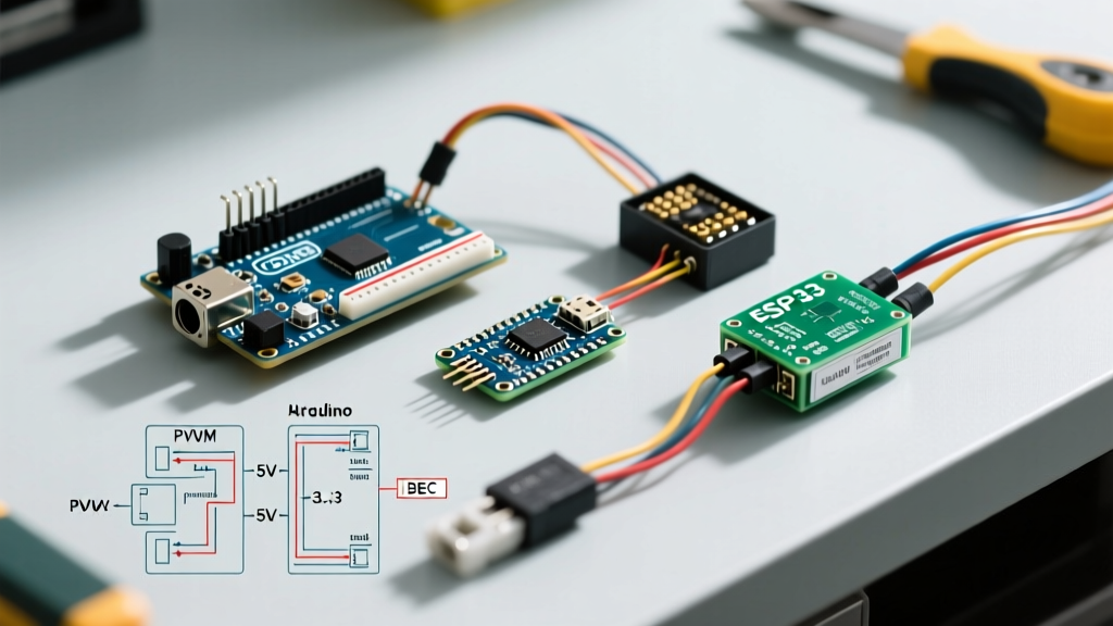
The Root Cause: BEC (Battery Eliminator Circuit) brownout. Most standard ESCs feature a linear 5V BEC that powers your Arduino via the servo plug's red wire. Under heavy motor load, electromagnetic interference (EMI) and voltage sag on the main battery line cause the linear BEC to drop from 5.0V down to 4.2V. If your Arduino's Brown-Out Detection (BOD) is set to 4.3V, the microcontroller instantly resets.
The Fix: Solder a 470µF to 1000µF, 25V Low-ESR electrolytic capacitor directly across the 5V and GND pins of the ESC's servo connector. This capacitor acts as a local energy reservoir, absorbing the high-frequency voltage spikes and bridging the microsecond voltage sags that trigger Arduino resets. Ensure the capacitor's voltage rating is at least 25V to handle inductive kickback spikes.
3. Opto-Isolated ESCs Refusing to Arm
The Symptom: You are using a high-end opto-isolated ESC (e.g., Hobbywing Platinum 60A Opto), but it remains completely dead. No beeps, no LED lights.
The Root Cause: Opto-isolated ESCs do not have a BEC. They physically separate the high-voltage motor side from the low-voltage logic side using optical isolators to prevent EMI from frying the microcontroller. Because there is no BEC, the ESC's internal logic board has no power source.
The Fix: You must supply 5V to the red wire of the ESC servo plug from an external source (like an Arduino 5V pin, provided your Arduino is powered via USB or a separate regulated buck converter). Do not rely on the Arduino's onboard 5V regulator if you are also powering multiple servos; use a dedicated 5V UBEC rated for at least 3A.
4. ESP32 vs. Arduino Uno PWM Timing Mismatches
The Symptom: Your code works perfectly on an Arduino Uno, but when you migrate to an ESP32 or the newer Arduino Uno R4 Minima, the ESC twitches erratically or refuses to arm.
The Root Cause: The ESP32 does not use the same ATmega hardware timers as the classic Uno. The standard PWM principles dictate a strict 50Hz frequency for ESCs, but the ESP32's native LEDC (LED Control) peripheral defaults to different frequencies, and older versions of the Servo library cause watchdog timer resets on dual-core ESP32s.
The Fix: For ESP32 boards, abandon the standard Servo library. Install the ESP32Servo library via the Library Manager, which correctly maps the LEDC channels to 50Hz. For the Arduino Uno R4 Minima (Renesas RA4M1), ensure you are using the latest official Arduino core, as early 2024 releases had known timer-mapping bugs with the Servo library that were patched in late 2025.
5. Ground Loop Interference & Signal Jitter
The Symptom: The motor spins, but it 'cog' or stutters at low RPMs, and you hear a high-pitched whining from the motor bells.
The Root Cause: A ground loop occurs when the high-current ground path (from the battery to the ESC) shares a thin wire with the logic ground (from the ESC to the Arduino). The massive current spikes from the BLDC motor create a voltage differential across the ground wire, which the Arduino interprets as noise on the PWM signal pin.
The Fix: Implement 'star grounding.' Connect the heavy battery ground directly to the ESC. Run a dedicated, separate ground wire from the ESC's servo plug ground pin directly to the Arduino's GND pin. Keep the PWM signal wire and its paired ground wire twisted together to reject common-mode EMI.
Component Spotlight: Recommended 2026 Hardware Pairings
Not all ESCs handle microcontroller signals equally. Based on current market availability and firmware reliability, here are the top pairings for Arduino projects:
- Hobbywing Skywalker 40A (~$24): Features a robust 3A switching BEC (far superior to linear BECs) and highly predictable arming timings. Ideal for Arduino-based rovers and boats.
- Turnigy Plush 30A (~$16): The budget king. Often shipped with SimonK firmware, which is incredibly responsive to rapid PWM changes, making it perfect for Arduino PID balancing robots.
- FLYCOLOR Raptor 50A Opto (~$28): Best for high-voltage (6S LiPo) Arduino drone builds. The opto-isolation protects your Arduino Nano from fatal voltage spikes during hard crashes.
Expert Code Snippet: Bulletproof Arming Routine
Stop using the basic Sweep example for ESCs. Use this robust initialization routine to guarantee a clean arming sequence every time your Arduino boots.
#include <Servo.h>

Servo esc;
const int escPin = 9; // Must be a hardware PWM pin

void setup() {
  // 1. Attach the ESC to the pin
  esc.attach(escPin, 1000, 2000); // Force strict 1000-2000us bounds

  // 2. Send absolute minimum throttle to satisfy arming requirement
  esc.writeMicroseconds(1000);

  // 3. Wait for the ESC to recognize the signal and arm (usually 2-3 beeps)
  // Do NOT use delay() in complex projects; use millis() for non-blocking waits
  unsigned long startTime = millis();
  while(millis() - startTime < 3000) {
    // Maintain the 1000us signal actively during the wait
    esc.writeMicroseconds(1000);
    delay(20); // Small delay to prevent flooding the timer
  }

  // 4. ESC is now armed. Proceed to your main loop.
}

void loop() {
  // Your motor control logic here
  // Example: esc.writeMicroseconds(1200); for low-speed spin
}
Final Verification Checklist
If you are still experiencing issues after applying these fixes, run through this final hardware checklist:
- Multimeter Check: Measure the voltage between the Arduino's 5V pin and the ESC's signal ground. It must read a stable 4.9V to 5.1V.
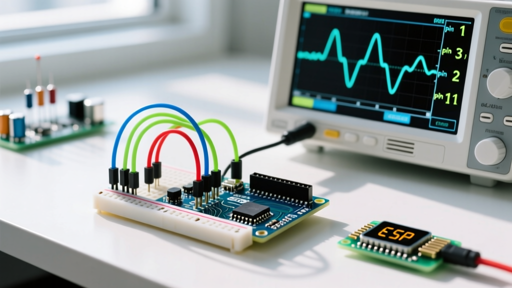
- Oscilloscope / Logic Analyzer: If you have access to a cheap $15 USB logic analyzer (like a Saleae clone), capture the PWM pin. Verify the period is exactly 20ms (50Hz) and the HIGH pulse is strictly between 1000µs and 2000µs.
- Throttle Calibration: Some ESCs require a manual throttle calibration. Power the ESC with the Arduino sending 2000µs. Wait for the 'beep-beep' confirmation, then drop the signal to 1000µs. Wait for the final confirmation tone. This maps the ESC's internal potentiometer limits to your Arduino's exact output.
Expert Tip: Never test an unverified ESC setup with a propeller attached. Always use a bare motor or a safely secured test jig. A misconfigured PWM pin can cause the motor to spin at 100% throttle the millisecond the Arduino powers on.