
The Hidden Cost of Prototyping Friction
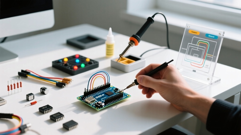
While cloud-based simulators and digital twins have matured significantly by 2026, physical hardware validation remains an unavoidable step in embedded engineering. For makers, students, and junior engineers, the Uno R3 Arduino starter kit represents the most critical bridge between theoretical code and physical reality. However, treating these kits as mere boxes of disjointed parts is a fundamental workflow mistake. When leveraged systematically, a well-organized Uno R3 Arduino starter kit becomes a rapid prototyping engine that eliminates bottlenecks, reduces debugging time, and accelerates the path from proof-of-concept to custom PCB design.
The official Arduino Uno R3 Starter Kit typically retails between $95 and $110, while high-quality third-party equivalents (like the Elegoo Super Starter Kit) hover around $35 to $45. Regardless of the brand, the underlying architecture relies on the ATmega328P-PU microcontroller. Understanding the physical and electrical limitations of the components inside this box is the first step toward optimizing your development workflow.
Deconstructing the Kit: Hardware That Impacts Speed
Not all components in a starter kit contribute equally to your workflow. Some accelerate development, while others introduce hidden friction. Here is a breakdown of the core kit components and how to manage them for maximum efficiency.
| Component | Specification | Workflow Impact & Optimization Strategy |
|---|---|---|
| Microcontroller Board | ATmega328P-PU (DIP-28), 16MHz | High Impact. The socketed DIP chip is a massive workflow advantage. If a 12V motor back-EMF spike fries the MCU, you can replace the $2.50 chip instead of trashing a surface-mount board. Always keep a spare ATmega328P-PU with the Optiboot bootloader in your inventory. |
| USB-to-Serial IC | ATmega16U2 (Official) or CH340G (Clone) | Medium Impact. The CH340G requires manual driver installation on older systems, causing setup delays. However, modern 2026 builds of Windows 11 and macOS handle CH340G natively. Verify your OS driver stack before starting a time-sensitive workshop. |
| Solderless Breadboard | 830 tie-points, ~0.1Ω contact resistance | High Impact. Breadboard contact resistance degrades over time. For I2C buses (SDA/SCL), keep wire lengths under 10cm to avoid parasitic capacitance that corrupts 400kHz Fast Mode signals. Reference SparkFun's breadboard guidelines for optimal rail usage. |
| Jumper Wires | AWG 24 / AWG 22 Dupont | High Impact. Cheap stranded wires fray and cause short circuits. Optimize your workflow by discarding frayed ends immediately and standardizing on rigid, U-shaped jumper wires for power rails to eliminate 'spaghetti' wiring. |
| Power Supply Module | MB-102 (3.3V / 5V selectable) | Critical for Actuators. The Uno's onboard AMS1117-5.0 LDO can only safely dissipate ~1W. At a 9V input, max current is ~120mA. Never run servos or 5V relays directly from the Uno's 5V pin; use the kit's breadboard power module to prevent thermal shutdown resets. |
The 4-Stage Prototyping Pipeline
To prevent the common trap of building a massive, untestable circuit on a single breadboard, adopt this four-stage pipeline when utilizing your Uno R3 Arduino starter kit. This methodology isolates variables and drastically reduces hardware debugging time.
- Stage 1: Logic Validation (Software-Only)
Before wiring a single sensor, write and compile the state machine or logic flow. Use the Serial Monitor to simulate sensor inputs via manual text commands. This ensures your C++ architecture is sound before introducing hardware noise. - Stage 2: Sub-Circuit Isolation (Hardware)
Test each peripheral individually on a secondary mini-breadboard (often included in premium kits). Verify I2C addresses using an I2C scanner sketch, and confirm SPI chip-select logic levels with a multimeter. Do not integrate until the sub-circuit is proven. - Stage 3: System Integration
Move proven sub-circuits to the main 830-point breadboard. Implement a strict color-coding standard: Red for 5V, Black for GND, Blue for 3.3V, and Yellow/Orange for signal lines. This visual hierarchy reduces troubleshooting time by up to 40%. - Stage 4: Power Profiling
Measure the total current draw. If your project exceeds 400mA, the standard USB 2.0 port (500mA limit) will become a bottleneck. Transition to a dedicated 5V 2A USB-C power bank or the kit's barrel-jack power supply to ensure stable voltage under load.
Wiring Discipline: Curing Breadboard Spaghetti
A chaotic breadboard is a workflow killer. When a circuit fails, debugging a 'rat's nest' of identical red jumper wires is nearly impossible. Professional engineers use wiring harnesses; makers must use spatial discipline.
Expert Insight: 'The most common cause of intermittent I2C failures in beginner kits isn't bad code; it's missing pull-up resistors and excessive wire capacitance. Always utilize the 4.7kΩ resistors included in your Uno R3 kit for SDA and SCL lines when interfacing with modules like the MPU6050 or OLED displays.' - Embedded Systems Best Practices, 2025 Edition
To optimize your physical layout, route all ground connections first, establishing a solid reference plane. Next, route power rails. Finally, route signal wires, keeping high-frequency lines (like SPI SCK or PWM outputs) as short and direct as possible to minimize electromagnetic interference (EMI) with sensitive analog inputs (A0-A5).
Edge Cases and Hardware Failure Modes
Even with a structured workflow, hardware edge cases will stall your progress. Recognizing these specific failure modes inherent to the Uno R3 ecosystem will save hours of frustration.
1. The AMS1117 Thermal Shutdown Loop
Symptom: The Uno randomly resets or the onboard voltage regulator becomes too hot to touch.
Root Cause: You are powering a 5V relay module (approx. 75mA) and an LCD backlight (approx. 50mA) from the Uno's 5V pin while supplying 12V via the barrel jack. The voltage drop (12V - 5V = 7V) multiplied by the current (125mA) equals 0.875W of heat, pushing the AMS1117 LDO to its thermal limit.
Workflow Fix: Bypass the onboard LDO. Use the breadboard power supply module included in your kit to feed 5V directly to the breadboard power rails, and connect the Uno's 5V pin to the rail to back-power the board safely.
2. Bootloader Corruption via Pin 0/1
Symptom: The IDE fails to upload sketches, throwing an 'avrdude: stk500_getsync() attempt 1 of 10' error.
Root Cause: Hardware attached to Digital Pins 0 (RX) and 1 (TX) is interfering with the UART serial handshake during the upload window.
Workflow Fix: Never wire external sensors to Pins 0 and 1 during the prototyping phase. Reserve these strictly for Serial Monitor debugging. If you must use hardware serial, implement a workflow where you physically disconnect the TX/RX jumper wires before clicking 'Upload' in the Arduino IDE.
3. Floating Analog Inputs
Symptom: Analog sensors (like LDRs or potentiometers) return erratic, jumping values in the Serial Monitor.
Root Cause: High-impedance voltage dividers without a bypass capacitor are susceptible to 50/60Hz mains hum and RF noise.
Workflow Fix: Utilize the ceramic capacitors (usually 104 / 0.1µF) included in the kit. Place one in parallel with the analog sensor's output to ground. Additionally, implement a software moving-average filter in your sketch to smooth out residual ADC quantization noise.
Transitioning from Kit to Production
The ultimate goal of the Uno R3 Arduino hardware is to make itself obsolete in your final product. Once your prototype is stable on the breadboard, your workflow must shift toward miniaturization and reliability.
Begin by migrating from the solderless breadboard to a perfboard or proto-shield using the kit's included header pins and solder. For the final production run, extract the ATmega328P-PU chip from the Uno's socket. Design a custom PCB that incorporates the MCU, the 16MHz crystal, the two 22pF load capacitors, and the 10kΩ reset pull-up resistor—all of which are standard components found in almost every comprehensive Uno R3 Arduino starter kit. This 'standalone ATmega' workflow reduces your final BOM cost from $25 down to roughly $3, while maintaining the exact firmware you developed during the prototyping phase.
Conclusion
A Uno R3 Arduino starter kit is not just a collection of LEDs and resistors; it is a complete laboratory for embedded systems development. By understanding the electrical limits of the AMS1117 regulator, enforcing strict wiring discipline, and utilizing a staged integration pipeline, you transform a simple box of parts into a highly optimized workflow engine. Master these physical constraints, and your transition from hobbyist prototyping to professional embedded engineering will be seamless.