
Hitting the ATmega328P Ceiling
If you have worked through the 30+ projects included in a standard Arduino ultimate starter kit (such as the popular Elegoo or Rexqualis bundles), you have likely mastered the fundamentals of embedded systems. You can debounce buttons, read DHT11 temperature sensors, drive SG90 servos, and write basic I2C routines. However, as your projects evolve from blinking LEDs to IoT telemetry, computer vision, or real-time signal processing, the ATmega328P-PU microcontroller at the heart of your Uno R3 clone becomes a severe bottleneck.
The ATmega328P offers just 2KB of SRAM, 32KB of Flash, and a 16MHz clock speed. When you attempt to buffer audio, parse JSON payloads from a cloud API, or drive high-resolution TFT displays, you will encounter memory fragmentation, stack overflows, and sluggish loop times. This guide provides a rigorous, engineering-focused migration path from the 8-bit AVR architecture to modern 32-bit ecosystems dominating the maker space in 2026.
The 2026 MCU Upgrade Matrix
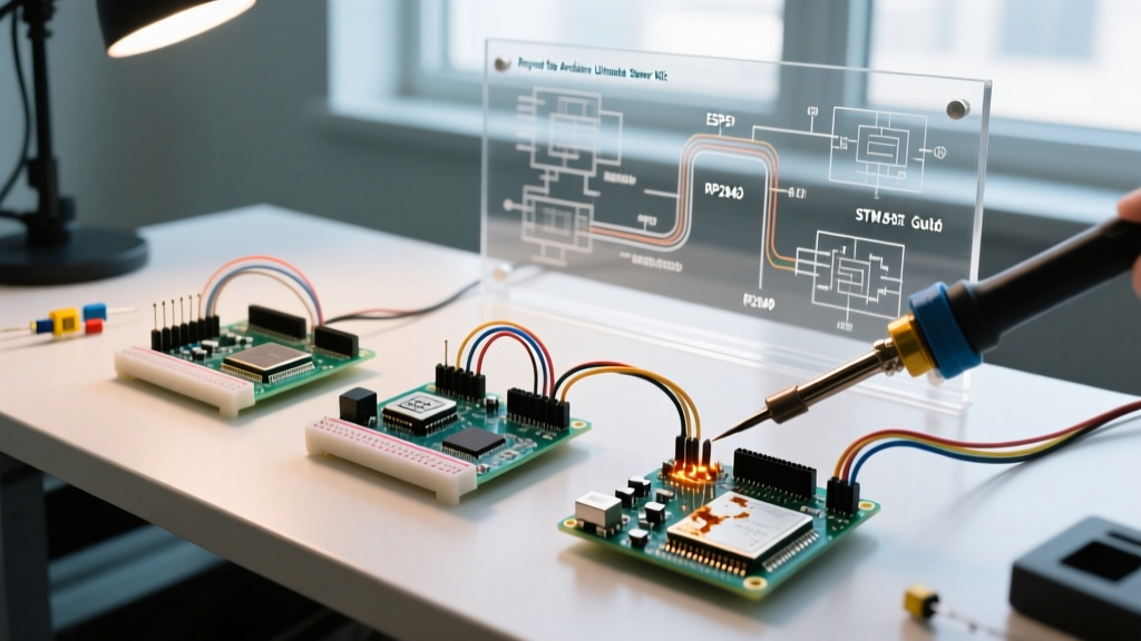
Choosing your next microcontroller depends entirely on your project's specific failure modes and requirements. Below is a technical comparison of the legacy AVR chip against the three primary upgrade paths.
| Specification | ATmega328P (Uno R3) | ESP32-S3 (IoT Path) | RP2040 (PIO/RTOS Path) | STM32F411CEU6 (DSP Path) |
|---|---|---|---|---|
| Architecture | 8-bit AVR | 32-bit Xtensa LX7 (Dual) | 32-bit ARM Cortex-M0+ | 32-bit ARM Cortex-M4F |
| Clock Speed | 16 MHz | 240 MHz | 133 MHz | 100 MHz |
| SRAM | 2 KB | 512 KB (+ 8MB PSRAM typical) | 264 KB | 128 KB |
| Flash | 32 KB | External (4MB - 16MB) | External (2MB - 16MB) | 512 KB |
| Logic Level | 5.0V | 3.3V | 3.3V | 3.3V |
| Typical 2026 DevKit Cost | $12.00 (Clone) | $7.50 (ESP32-S3-DevKitC-1) | $6.00 (Raspberry Pi Pico W) | $5.50 (WeAct Black Pill) |
Migration Path 1: The IoT Leap to ESP32-S3
If your goal is to connect your projects to AWS IoT, Home Assistant, or MQTT brokers, the ESP32-S3 is the definitive upgrade. Unlike the original ESP32 (v1), the S3 variant includes native USB OTG and vector instructions for AI acceleration, making it vastly superior for edge computing.
IDE and Board Manager Configuration
To migrate your sketches, you must install the Espressif ESP32 Arduino Core via the Arduino IDE Boards Manager. Search for esp32 by Espressif Systems and install version 3.x or newer.
- Board Selection: Choose ESP32S3 Dev Module.
- USB CDC On Boot: Set to Enabled to allow standard
Serial.println()debugging over the native USB port. - Flash Size: Configure to match your specific devkit (usually 4MB or 8MB).
Pin Mapping and Peripheral Differences
The most immediate friction point when migrating from an Uno is pin mapping. The ESP32-S3 does not use the standard Arduino digital pin numbers (0-13). You must address GPIOs directly. For example, the built-in LED is typically on GPIO48, not LED_BUILTIN (unless defined by the specific board variant). Furthermore, GPIOs 0-20 on the S3 are often reserved for internal SPI flash and PSRAM; using them for external sensors will cause boot loops.
Migration Path 2: Deterministic Timing with RP2040
If your projects require precise signal generation, custom protocols (like WS2812B LED matrices or bespoke RF decoding), or dual-core RTOS management, the Raspberry Pi RP2040 is your target. The Raspberry Pi Pico Documentation highlights the Programmable I/O (PIO) state machines, which offload timing-critical tasks from the main CPU cores.
Refactoring for Dual-Core Execution
The RP2040 features two Cortex-M0+ cores. To utilize both in the Arduino IDE, you use the multicore API. Moving your sensor polling to Core 1 while Core 0 handles Wi-Fi (if using the Pico W) or display rendering eliminates the blocking delays that plague single-core AVR sketches.
Engineering Warning: When migrating I2C devices from your starter kit to the Pico, remember that the Pico's default I2C pins are not the same as the Uno's A4/A5. I2C0 defaults to GPIO4 (SDA) and GPIO5 (SCL), while I2C1 defaults to GPIO26 and GPIO27. You can remap these via the IDE, but hardcoding the defaults ensures compatibility with standard Pico HATs.
The 5V to 3.3V Trap: Hardware Edge Cases
The single most common cause of hardware failure during this migration is ignoring logic level differences. The sensors included in your Arduino ultimate starter kit (HC-SR04 ultrasonic, standard 16x2 I2C LCDs, 5V relay modules) operate at 5V. The ESP32-S3, RP2040, and STM32 are strictly 3.3V devices. Applying 5V to a 3.3V GPIO will permanently degrade or destroy the silicon.
Sensor-Specific Migration Fixes
- HC-SR04 Ultrasonic Sensor: The
Echopin outputs a 5V pulse. Do not connect this directly to an ESP32. Use a simple voltage divider (a 1kΩ resistor in series with the Echo pin, and a 2kΩ resistor to ground) to drop the 5V signal to a safe 3.3V. Alternatively, upgrade to the HC-SR04P, which natively operates at 3.3V. - I2C LCDs and OLEDs: I2C is bidirectional. A simple voltage divider will not work because the MCU needs to pull the SDA line low. You must use a dedicated I2C level shifter like the NXP PCA9306 or the Texas Instruments TXB0108 for general bidirectional GPIO translation.
- 5V Relay Modules: Most optocoupler-based relay modules require a 5V VCC and a 5V trigger signal. Replace these with 3.3V logic-level MOSFET modules or relays specifically rated for 3.3V trigger thresholds to avoid brownouts on the ESP32's onboard 3.3V LDO.
Software Porting: Hidden 32-Bit Architecture Bugs
Migrating code from an 8-bit AVR to a 32-bit ARM or RISC-V architecture introduces subtle data-type bugs that will compile perfectly but fail at runtime.
The Integer Overflow Shift
On the ATmega328P, an int is 16 bits (range: -32,768 to 32,767). On the ESP32 and RP2040, an int is 32 bits (range: -2,147,483,648 to 2,147,483,647). If your starter kit code relied on 16-bit integer overflow for timing or circular buffers, it will break on 32-bit MCUs.
Fix: Audit your code and replace generic int declarations with explicitly sized types from <stdint.h>. Use int16_t, uint8_t, and uint32_t to guarantee identical behavior across architectures. Refer to the Microchip ATmega328P Datasheet to verify legacy register sizes during porting.
Analog Resolution Scaling
The Uno's ADC is 10-bit (0-1023). The ESP32-S3 and RP2040 feature 12-bit ADCs (0-4095). If you have hardcoded thresholds for analog sensors (e.g., if (analogRead(LDR_PIN) > 800)), the sensor will appear entirely unresponsive on the new hardware because the 12-bit value will easily exceed 2000 in the same lighting conditions.
Fix: Normalize your analog reads immediately after polling. Use the Arduino map() function or bitwise shifting (analogRead(pin) >> 2) to scale 12-bit values back down to 10-bit equivalents if you want to preserve legacy threshold logic.
Power Supply Considerations for Advanced Kits
The Uno R3 features a robust, albeit inefficient, linear regulator that can accept 7-12V via the barrel jack. Modern ESP32 and RP2040 devkits typically rely on USB 5V input and use onboard switching regulators or LDOs to step down to 3.3V.
When migrating battery-powered projects from your starter kit, do not feed 9V battery snaps into the VIN pin of an ESP32 DevKit. Most DevKits lack the thermal dissipation to handle the voltage drop from 9V to 3.3V at high Wi-Fi transmission currents (which can spike to 450mA). Instead, use a dedicated LiPo battery with a 3.3V switching step-up/step-down regulator (like the Pololu S7V8F3) to feed the 3.3V pin directly, bypassing the inefficient onboard LDO and extending battery life by up to 40%.
Summary of the Migration Workflow
Upgrading from an Arduino ultimate starter kit is a rite of passage. By systematically addressing the logic level mismatches, refactoring your data types for 32-bit architectures, and selecting the correct MCU for your specific bottleneck (IoT vs. PIO vs. DSP), you transition from a hobbyist assembling tutorials to an embedded engineer designing robust, production-ready firmware.