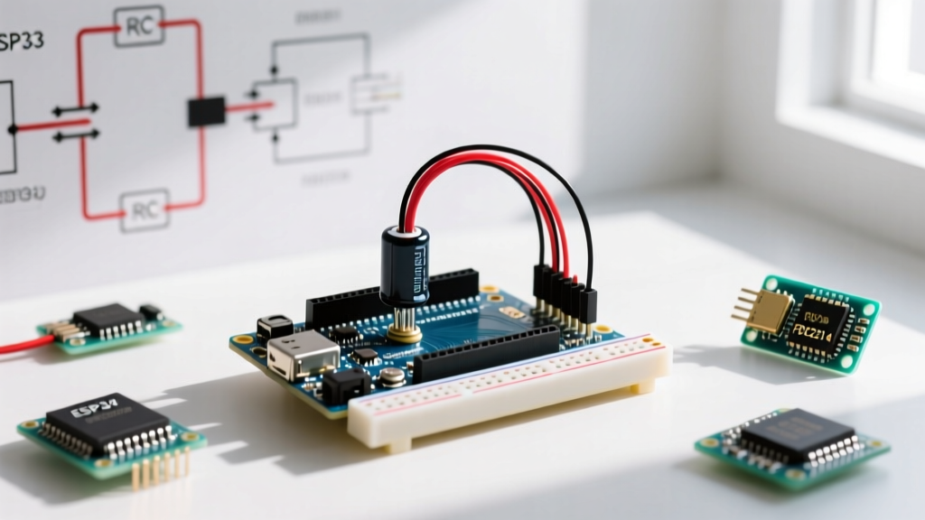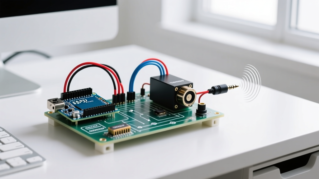

The Modern Arduino Loudspeaker Workflow
Building an Arduino loudspeaker used to mean accepting severe compromises: tinny 8-bit PWM audio, maxed-out CPU cycles, and a tangled mess of jumper wires. As we navigate the maker landscape in 2026, the ecosystem has matured dramatically. With the widespread availability of 32-bit microcontrollers like the ESP32-S3 and cheap, high-efficiency I2S Class-D amplifiers, you can now achieve CD-quality audio output without writing a single line of assembly.
However, hardware availability does not automatically translate to a smooth build process. Many makers still fall into the trap of inefficient prototyping—spending hours debugging ground loops, audio stuttering, and clipping issues that could have been avoided with a structured workflow. This guide outlines an optimized, end-to-end pipeline for designing, wiring, programming, and testing Arduino-based loudspeaker systems.
Phase 1: Component Selection Matrix
The most critical workflow bottleneck occurs when you select the wrong audio output method for your specific use case. Before writing a single line of code, map your project requirements against the hardware matrix below.
| Audio Method | Hardware Stack | Resolution / Sample Rate | CPU Overhead | Approx. Cost (2026) | Workflow Verdict |
|---|---|---|---|---|---|
| Direct PWM | ATmega328P + RC Filter | 8-bit / 32kHz | Extreme (Timer1 hijacked) | $1.00 | Avoid. Only for simple beep/alert tones. |
| R-2R Ladder DAC | Arduino Due + Resistor Network | 12-bit / 44.1kHz | High (Parallel writes) | $3.50 | Legacy. Bulky wiring, prone to noise. |
| I2S Digital Audio | ESP32-S3 + MAX98357A | 16-bit to 32-bit / 44.1kHz+ | Near Zero (DMA driven) | $7.50 | Optimal. Best fidelity, frees up CPU. |
| MP3/Audio Shield | Arduino Uno + VS1053 Shield | 16-bit / 48kHz (Decoded) | Low (SPI streaming) | $24.99 | Niche. Best for SD-card MP3 playback. |
For 90% of modern Arduino loudspeaker projects—ranging from smart home voice assistants to custom synthesizers—the I2S Digital Audio route using an ESP32 variant and a MAX98357A breakout board is the undisputed champion. It leverages Direct Memory Access (DMA), meaning the audio buffer is fed to the speaker in the background while your main loop handles Wi-Fi, sensors, and UI logic.
Phase 2: Optimized Wiring and Grounding Strategy
Audio circuits are unforgiving of poor wiring practices. A common failure mode in Arduino loudspeaker prototypes is a persistent 50/60Hz hum or high-frequency digital whine. This is almost always a ground loop or power rail noise issue.
The Star Grounding Protocol
Never chain your audio ground through your digital sensor grounds. Implement a star grounding topology:
- Identify a single physical point on your power distribution board or prototype PCB to act as the "Star Point."
- Run the ground wire from your power supply directly to this Star Point.
- Run separate, dedicated ground wires from the Star Point to the microcontroller's GND pin and the I2S amplifier's GND pin.
- Keep digital signal grounds (like I2C sensors) isolated from the audio ground return path.
Power Supply Decoupling
Class-D amplifiers like the MAX98357A or PAM8403 draw sudden, high-current bursts during bass transients. If your power rail sags, the microcontroller will brown out and reset. To optimize your workflow and eliminate intermittent resets, always place a decoupling network as close to the amplifier's VCC pin as physically possible:
- 100nF (0.1µF) Ceramic Capacitor: Filters high-frequency switching noise generated by the Class-D amp itself.
- 100µF to 470µF Electrolytic Capacitor: Acts as a local energy reservoir to handle low-frequency bass transients without pulling from the main USB/battery rail.
Pro-Tip: When transitioning from breadboard to perfboard, abandon rigid Dupont jumper wires for power and ground. Use 24 AWG stranded silicone wire. It handles the current spikes of a 3.2W loudspeaker without voltage drop and prevents cold solder joints caused by wire stiffness.
Phase 3: Software Stack and Non-Blocking Audio
The biggest mistake makers make when building an Arduino loudspeaker is using blocking audio functions. If you use a basic `delay()` or a blocking tone library, your microcontroller cannot read buttons, update displays, or maintain Wi-Fi connections while audio plays.
Choosing the Right Library
Depending on your audio source, select your software stack carefully:
- For Synthesizers and Generative Audio: Use the Mozzi sonification library. It is heavily optimized for real-time audio synthesis, allowing you to generate complex waveforms, FM synthesis, and envelopes without starving your main control loop.
- For Streaming and File Playback (ESP32): Utilize the native I2S driver. The Espressif I2S API documentation provides robust DMA buffer configurations that guarantee glitch-free audio even under heavy Wi-Fi loads.
DMA Buffer Tuning for ESP32
When configuring the I2S driver on an ESP32-S3 for a loudspeaker, default buffer settings often cause stuttering if the CPU experiences a Wi-Fi interrupt. Optimize your `i2s_driver_install` configuration with these specific parameters:
dma_buf_count = 8(Allocates 8 distinct DMA buffers to absorb CPU latency spikes).dma_buf_len = 64(Keeps individual buffer sizes small enough to maintain low latency for real-time synth key-presses).- Always ensure your I2S
bits_per_samplematches your DAC's hardware expectation (usually 16-bit or 32-bit for the MAX98357A).
Phase 4: Acoustic Testing and Enclosure Workflow
An Arduino loudspeaker project is only as good as its acoustic output. Testing a raw speaker driver resting on a workbench yields useless data due to phase cancellation (sound waves from the back of the cone wrapping around and canceling the front waves).
The Infinite Baffle Quick-Test
Before committing to a 12-hour 3D print for a custom enclosure, build a quick "infinite baffle" test rig. Mount your speaker driver into a scrap piece of 1/2-inch MDF or acrylic with a precisely cut circular hole. Seal the edges with hot glue. This immediately eliminates acoustic short-circuiting and allows you to accurately evaluate the amplifier's EQ and volume scaling.
Measuring with REW
Skip the subjective "ear test." Download Room EQ Wizard (REW) (free, industry-standard acoustic software). Connect a calibrated USB measurement microphone to your PC. Generate a 20Hz–20kHz sine sweep from your PC, route it through your microcontroller via Bluetooth or serial, and play it out of your Arduino loudspeaker. REW will instantly map the frequency response, revealing if your enclosure is causing a resonance peak at 150Hz or if your Class-D amp is rolling off the high frequencies above 12kHz.
Troubleshooting Edge Cases and Failure Modes
Even with an optimized workflow, edge cases occur. Here is how to rapidly diagnose the three most common Arduino loudspeaker failures:
1. High-Frequency Hiss (White Noise)
Cause: The I2S amplifier's gain is set too high, amplifying the inherent noise floor of the microcontroller's power rail.
Fix: The MAX98357A features a hardware gain pin. Pull the GAIN pin to GND for 9dB (ideal for line-level signals) or leave it floating for 15dB. Do not rely on software volume reduction if the hardware noise floor is already clipping the amplifier's input stage.
2. Audio Clipping and Distortion at High Volume
Cause: Software volume is set to 100%, but the DAC output voltage exceeds the amplifier's input tolerance, or the power supply is browning out.
Fix: Implement a software limiter in your audio pipeline. Cap your digital audio amplitude at -3dBFS (roughly 70% of maximum integer value) before sending it to the I2S DMA buffer. This provides headroom for inter-sample peaks.
3. I2S Clock Sync Dropouts
Cause: Bit Clock (BCLK) and Left-Right Clock (LRCLK) signals are degrading over long, unshielded breadboard wires.
Fix: I2S is highly sensitive to signal integrity. Keep BCLK, LRCLK, and DIN wires under 10 centimeters in length. If you must run them further, use a logic level shifter with active drive capabilities or twisted-pair wiring to prevent capacitive crosstalk.
Conclusion
Building a high-fidelity Arduino loudspeaker in 2026 is less about brute-forcing PWM timers and more about intelligent system architecture. By selecting an I2S-based hardware stack, enforcing strict star-grounding wiring protocols, leveraging DMA-backed audio libraries, and validating your acoustics with proper measurement tools, you eliminate the trial-and-error phase. This optimized workflow ensures that your time is spent refining the user experience and audio quality, rather than chasing digital noise with an oscilloscope.