
The Strategic Value of ICSP Arduino Configuration
When designing custom printed circuit boards (PCBs) or recovering bricked ATmega328P microcontrollers in 2026, relying solely on the UART serial bootloader is insufficient. In-Circuit Serial Programming (ICSP) provides a direct, low-level communication pathway to the AVR silicon, bypassing the bootloader entirely. Whether you need to reclaim the 1.5KB of flash memory occupied by the Optiboot bootloader, modify clock speed fuse bits, or mass-program bare chips before soldering, mastering the ICSP Arduino workflow is a mandatory skill for advanced makers and embedded engineers.
Unlike standard serial uploads that require a pre-existing bootloader and a USB-to-Serial bridge, ICSP utilizes the SPI (Serial Peripheral Interface) bus. This allows you to write directly to the flash memory, EEPROM, and configuration fuses of the microcontroller. According to the official Arduino ISP Documentation, this method is the only way to restore a chip that has suffered a corrupted bootloader or incorrect fuse settings that disabled the reset pin.
Hardware Matrix: Selecting the Right ICSP Programmer
Choosing the correct hardware programmer dictates your flashing speed, reliability, and budget. Below is a comparison of the most prevalent ICSP programmers used in the Arduino ecosystem today.
| Programmer Model | Avg. Price (2026) | Interface | Best Use Case |
|---|---|---|---|
| USBasp (Clone) | $6 - $12 | USB 2.0 | Hobbyist flashing, basic bootloader burning |
| Pololu USB AVR Programmer v2.1 | $22 - $28 | USB 2.0 | Reliable production, adjustable VCC targeting |
| Atmel-ICE (Microchip) | $135 - $150 | USB 2.0 | Professional debugging, PDI/UPDI/SPI, JTAG |
| Arduino as ISP | $25 (Uno cost) | UART/USB | Emergency recovery, field repairs without extra tools |
Expert Tip: If you are using an Atmel-ICE, remember that it natively outputs a 10-pin Cortex debug header. You must use a 10-pin to 6-pin adapter board to connect to the standard Arduino ICSP header.
Standard 6-Pin ICSP Header Pinout and Wiring Specifics
The physical connection for ICSP Arduino configurations relies on a standardized 2x3 pin header. Misaligning this cable is the most common cause of failed flashes and, in worst-case scenarios, can short 5V to ground, damaging your programmer. Always verify the pinout against the silkscreen on your custom PCB or the official Arduino Uno schematics.
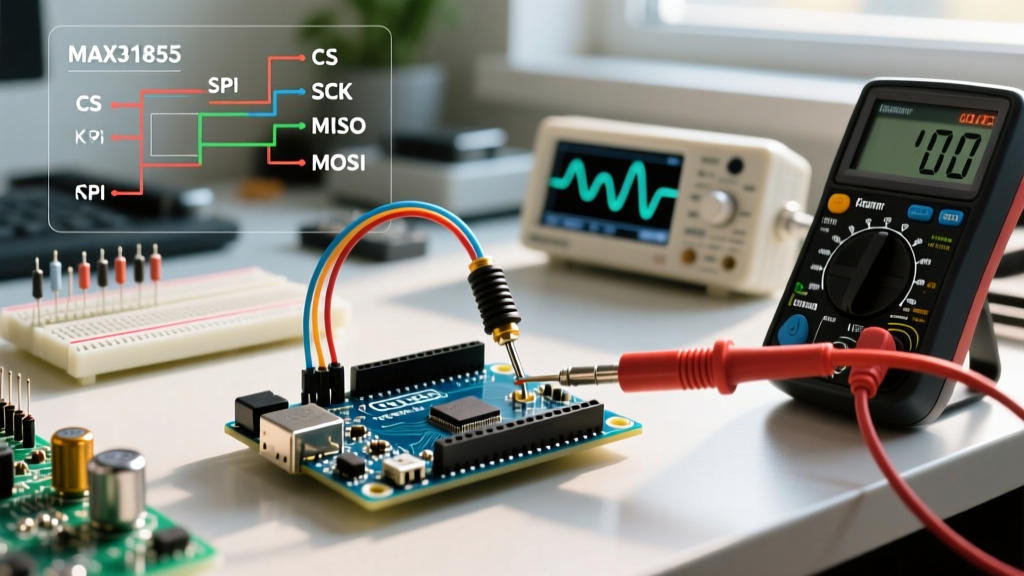
- Pin 1 (MISO): Master In Slave Out. Data flowing from the target AVR to the programmer.
- Pin 2 (VCC): 5V Power. Powers the target chip. Ensure your programmer can supply adequate current (usually 500mA max).
- Pin 3 (SCK): Serial Clock. The timing signal generated by the programmer.
- Pin 4 (MOSI): Master Out Slave In. Data flowing from the programmer to the target AVR.
- Pin 5 (RESET): Active low reset. Pulled low by the programmer to enter programming mode.
- Pin 6 (GND): Ground reference. Must be shared between programmer and target.
Phase 1: Burning a Bootloader via the Arduino IDE
If you have soldered a fresh ATmega328P-PU chip onto a custom board, it lacks the Arduino bootloader and default fuse settings. It will not accept serial sketches until configured. The Arduino IDE simplifies this via its graphical interface.
- Connect your ICSP programmer to the 6-pin header and plug it into your PC via USB.
- Open the Arduino IDE and navigate to Tools > Programmer. Select your specific hardware (e.g., 'USBasp' or 'Atmel-ICE').
- Ensure the correct board is selected under Tools > Board (e.g., 'Arduino Uno').
- Click Tools > Burn Bootloader.
The IDE will invoke AVRDUDE in the background, writing the Optiboot hex file to the uppermost pages of flash memory and setting the 'High Fuse' to allocate 256 words for the boot section. This process typically takes 8 to 12 seconds.
Phase 2: Direct Sketch Upload and Flash Reclamation
For memory-constrained projects, the 1.5KB bootloader overhead is unacceptable. By uploading directly via ICSP, you utilize 100% of the 32KB flash space. Furthermore, direct uploads execute instantly upon power-up, eliminating the standard 1-second bootloader delay.
To compile without uploading, click the 'Verify' button in the Arduino IDE. Locate the compiled .hex file in your temporary build folder (enable verbose output in Preferences to see the exact path). You can then flash this file using the command line.
AVRDUDE Command Line Syntax
AVRDUDE is the industry-standard engine for AVR programming. The official AVRDUDE documentation details hundreds of flags, but a standard direct flash command for a USBasp programmer looks like this:
avrdude -c usbasp -p m328p -B 4 -U flash:w:firmware_v2.hex:i-c usbasp: Specifies the programmer type.-p m328p: Specifies the target microcontroller (ATmega328P).-B 4: Sets the bit clock period to 4 microseconds. Crucial if the target chip is running on a slow internal oscillator (e.g., 1MHz factory default).-U flash:w:...: Instructs AVRDUDE to write the intel-hex file to the flash memory.
Advanced Configuration: Modifying AVR Fuse Bits
Fuse bits are non-volatile configuration bytes that dictate the fundamental hardware behavior of the AVR chip. They are not erased when you flash new code. According to the Microchip ATmega328P Datasheet, there are three fuse bytes: Low, High, and Extended.
Misconfiguring these can soft-brick your chip. For example, disabling the SPIEN (SPI Enable) fuse bit will permanently lock out ICSP programming, requiring a high-voltage parallel programmer to recover. The standard fuse configuration for an Arduino Uno running at 16MHz with an external crystal is:
| Fuse Byte | Hex Value | Key Configurations Enabled |
|---|---|---|
| Low Fuse | 0xFF | External Crystal Oscillator (8.0- MHz), 16K CK/14 CK + 65ms startup |
| High Fuse | 0xDE | SPIEN enabled, BOOTRST enabled, Boot Flash size = 256 words |
| Extended Fuse | 0xFD | Brown-out Detection (BOD) enabled at 2.7V |
To manually write these fuses via AVRDUDE, append the following flags to your command:
-U lfuse:w:0xFF:m -U hfuse:w:0xDE:m -U efuse:w:0xFD:mTroubleshooting Common ICSP Failures
Even with perfect wiring, environmental and configuration variables can cause ICSP sync failures. Use this diagnostic matrix to resolve errors rapidly.
1. 'avrdude: initialization failed, rc=-1'
Cause: The programmer cannot establish an SPI clock sync with the target. This usually happens when the target chip is running on its factory-default 1MHz internal oscillator, but the programmer is attempting to communicate at a faster rate.
Solution: Lower the bit clock rate by adding the -B 125 flag to your AVRDUDE command, or use the 'Slow SCK' jumper on older USBasp clones.
2. 'Yikes! Invalid device signature' or 'Expected signature for ATmega328P is 1E 95 0F'
Cause: AVRDUDE is reading the wrong silicon ID. This occurs if MISO and MOSI are swapped, if the target chip is completely dead, or if the wrong chip is selected in the IDE.
Solution: Verify continuity on the MISO and MOSI lines with a multimeter. Ensure the chip is receiving a stable 5V on the VCC pin during the programming sequence.
3. Target Works on Breadboard but Fails on Custom PCB
Cause: Missing decoupling capacitors or an unconnected RESET pull-up resistor. The ATmega328P requires a 100nF ceramic capacitor placed as close to the VCC/GND pins as possible to stabilize the internal logic during high-current flash write cycles.
Solution: Add a 10kΩ pull-up resistor from the RESET pin to 5V, and ensure a 100nF capacitor is soldered directly across pins 7 and 8 (DIP package) or their SMD equivalents.
Summary of Best Practices
Mastering the ICSP Arduino configuration transforms you from a casual module-assembler into a capable embedded systems designer. Always keep a dedicated 'Arduino as ISP' setup in your toolkit for emergency recoveries, invest in a genuine Pololu or Microchip programmer for reliable production runs, and never modify fuse bits without consulting the official datasheet and calculating the hex values using a verified fuse calculator. By leveraging direct ICSP flashing, you maximize silicon potential, eliminate boot delays, and ensure robust firmware deployment across all your custom hardware designs.