
Decoding the 38kHz Standard: Why Module Choice Dictates Project Success
When integrating infrared remote controls into maker projects, selecting the right ir receiver module arduino enthusiasts rely on is rarely as simple as grabbing the first breakout board from a bin. While the fundamental premise of IR communication remains unchanged—modulating a 940nm infrared beam at a specific carrier frequency (usually 38kHz) to transmit baseband data—the silicon inside the receiver dictates your project's reliability, range, and microcontroller compatibility.
In 2026, the market is flooded with seemingly identical black epoxy modules. However, beneath the surface, critical differences in Automatic Gain Control (AGC) algorithms, supply voltage tolerances, and output stage architectures separate professional-grade components from frustratingly inconsistent clones. This guide dissects the hardware realities of the most common IR receivers, ensuring your next remote-controlled robot, smart home relay, or media center interface operates flawlessly.
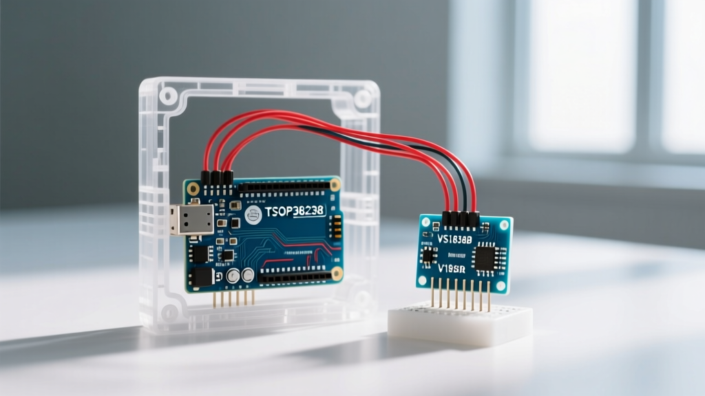
The Core Contenders: TSOP38238 vs. VS1838B vs. KY-022
To understand compatibility, we must first identify the silicon. Most hobbyist modules fall into three distinct categories, each with unique electrical characteristics.
| Module / IC Type | Typical IC Origin | Supply Voltage | Output Type | Avg. Cost (2026) | Best Use Case |
|---|---|---|---|---|---|
| TSOP38238 | Vishay Semiconductors | 2.5V to 5.5V | Push-Pull (Active Low) | $1.80 - $2.95 | Precision timing, battery-powered IoT, 3.3V MCUs |
| VS1838B | Various (Generic/Clone) | 3.3V to 5.0V | Push-Pull (Active Low) | $0.15 - $0.40 | Basic 5V Arduino Uno/Nano indoor projects |
| KY-022 | Sensor Kit Breakout (Uses VS1838B or HX1838) | 3.3V to 5.0V | Push-Pull w/ Onboard LED | $0.90 - $1.50 | Rapid prototyping on 5V breadboards |
The Adafruit IR Sensor overview frequently highlights the superiority of the Vishay TSOP series for environments with high optical noise. The TSOP38238 features an advanced AGC circuit specifically designed to suppress continuous 38kHz noise (like that from sunlight or specific fluorescent ballasts) without blinding the receiver to valid remote control bursts.
Voltage Logic and Microcontroller Compatibility
The most common point of failure when wiring an ir receiver module arduino setups experience is a mismatch in logic levels and voltage sag, particularly when migrating from 5V AVR boards to 3.3V ARM or RISC-V architectures.
The 3.3V ESP32 and RP2040 Trap
If you are using an ESP32, Raspberry Pi Pico (RP2040), or an Adafruit Feather, you are operating on 3.3V logic. While the datasheets for the generic VS1838B claim a minimum operating voltage of 3.3V, real-world edge cases reveal a hidden flaw in the ubiquitous KY-022 breakout board.
⚠️ Hardware Warning: The standard KY-022 module includes a power indicator LED and a current-limiting resistor wired in parallel with the IR receiver's power rails. On a 5V Arduino Uno, this is negligible. On a 3.3V ESP32, the forward voltage drop of the LED combined with the module's internal quiescent current can cause the VCC pin to sag below 2.9V under load, resulting in erratic decoding or total module brownouts.
The Fix: If you must use a KY-022 on a 3.3V microcontroller, desolder the onboard power LED, or bypass the module's onboard 3.3V regulator (if present) by feeding it directly from a stable 5V rail while using a logic level shifter or a simple voltage divider on the OUT pin to protect your ESP32's GPIO.
Environmental Edge Cases: AGC Saturation in Modern Lighting
A frequent complaint in maker forums is an IR receiver that works perfectly on the workbench but fails when installed in a living room. This is rarely a code issue; it is an environmental hardware limitation.
The LED Driver Interference Phenomenon
Modern smart bulbs and high-efficiency LED drivers utilize high-frequency Pulse Width Modulation (PWM) to dim the lights. While the visible light is modulated at kHz frequencies, poorly filtered switching power supplies inside these bulbs can emit broad-spectrum infrared noise that overlaps the 30kHz–40kHz band.
- Generic VS1838B: When exposed to this continuous IR noise, the internal AGC aggressively increases its detection threshold to prevent false triggers. Consequently, the receiver becomes 'deaf' to the lower-power signals from your handheld remote, reducing effective range from 8 meters to under 1 meter.
- Vishay TSOP38238: Utilizes a sophisticated band-pass filter and an integration circuit that distinguishes between continuous noise and the specific burst-gap patterns of NEC or RC5 remote protocols. It maintains full range even in rooms saturated with smart LED noise.
IRremote Library v4.x+ Implementation Guide
Hardware compatibility is only half the battle. The definitive Arduino IRremote Library on GitHub underwent massive architectural changes in its v4.0+ releases, deprecating the old `IRrecv` object in favor of a more memory-efficient `IrReceiver` instance.
Below is the modern, optimized boilerplate for initializing a TSOP38238 or VS1838B on pin 2 of an Arduino Uno or Nano.
#include <IRremote.hpp>

const int IR_RECEIVE_PIN = 2;

void setup() {
    Serial.begin(115200);
    // v4.x+ syntax: Disables LED feedback on pin 13 to prevent PWM conflicts
    IrReceiver.begin(IR_RECEIVE_PIN, DISABLE_LED_FEEDBACK);
    Serial.println(F("IR Receiver Ready - Waiting for NEC/RC5 Signals..."));
}

void loop() {
    if (IrReceiver.decode()) {
        // Print the raw protocol data for debugging
        IrReceiver.printIRResultShort(&Serial);

        // Example: Check for a specific NEC power button hex code
        if (IrReceiver.decodedIRData.protocol == NEC &&
            IrReceiver.decodedIRData.command == 0x45) {
            Serial.println(F("Power Button Pressed!"));
        }

        IrReceiver.resume(); // Critical: Re-enable the receiver interrupt
    }
}
Pro-Tip for ESP32 Users: The ESP32's hardware timers can sometimes conflict with the default timer assignments in the IRremote library. If you experience compile errors or missed interrupts, explicitly define the timer before calling `IrReceiver.begin()` by adding `#define USE_IRREMOTE_HPP_AS_PLAIN_INCLUDE` or consulting the library's ESP32-specific hardware timer documentation.
Expert Troubleshooting Matrix
When your ir receiver module arduino circuit fails to decode signals, use this diagnostic matrix to isolate the fault before rewriting your sketch.
| Symptom | Probable Root Cause | Hardware / Software Solution |
|---|---|---|
| Serial monitor prints 'UNKNOWN' protocol for every button. | Carrier frequency mismatch. Remote is transmitting at 36kHz or 40kHz, while receiver is tuned to 38kHz. | Verify remote carrier frequency. Swap TSOP38238 for a TSOP38236 (36kHz) or TSOP38240 (40kHz) variant. |
| Range is limited to < 10cm; works fine when remote is touching the sensor. | AGC saturation from ambient light or VCC ripple from a noisy switching buck converter. | Add a 100µF electrolytic capacitor and a 0.1µF ceramic capacitor directly across the VCC and GND pins of the IR module. |
| Receiver works on Uno, but returns no data on ESP32. | GPIO pin conflict. ESP32 GPIOs 6-11 are connected to the integrated SPI flash and cannot be used for IR interrupts. | Move the IR OUT wire to a safe RTC GPIO, such as GPIO 15, 16, or 17. Update `IR_RECEIVE_PIN` in code. |
| Ghost readings (triggering commands without pressing a button). | Floating data line or EMI from nearby AC relays. | Ensure the module has an internal pull-up. If using a bare TSOP IC, add a 10kΩ external pull-up resistor to VCC. |
Final Recommendations for Makers
For educational kits, basic 5V relay triggers, and indoor prototypes where budget is the primary constraint, the generic VS1838B remains a viable, cost-effective workhorse. However, as projects evolve into permanent smart home installations, battery-operated wearables, or environments dominated by modern LED lighting, upgrading to a genuine Vishay TSOP38238 is not just a luxury—it is a necessity for reliable data packet acquisition.
By matching the receiver's AGC capabilities, voltage requirements, and logic outputs to your specific microcontroller and environment, you eliminate the most common points of failure in IR communication. For further reading on optical sensor integration, the SparkFun IR Control Hookup Guide provides excellent supplementary schematics for advanced multi-emitter arrays.