
The Limits of USB Power in Modern Prototyping
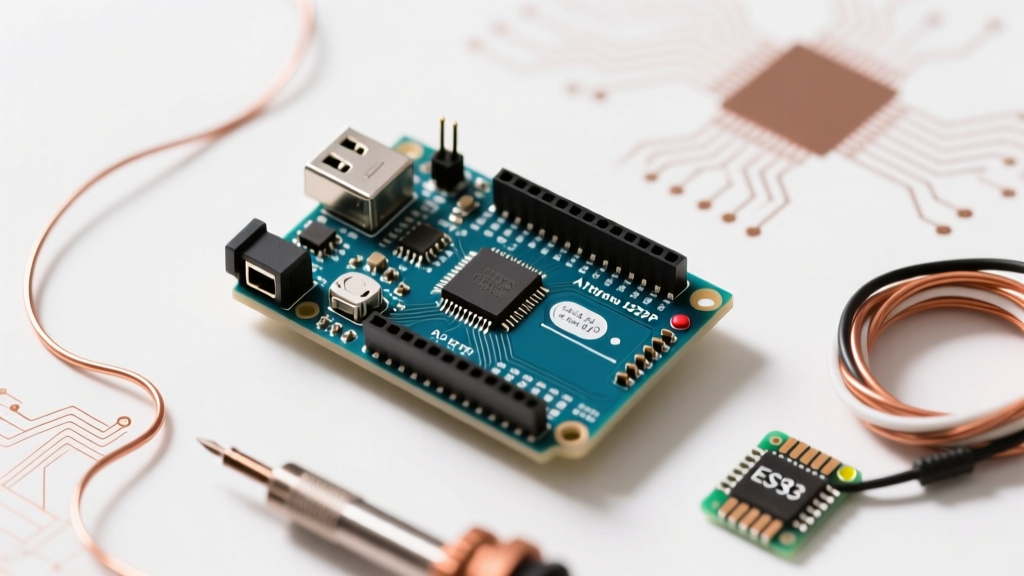
When you first unbox an Arduino Uno R3 or Nano, powering it via a standard USB-A cable seems like the perfect solution. However, USB 2.0 ports are hardware-limited to 500mA, and USB 3.0 ports cap at 900mA. More importantly, the classic Arduino Uno R3 features a resettable polyfuse (typically a 500mA RXE series component) on the USB VBUS line. The moment your project incorporates high-draw components like MG996R servos, 12V relay modules, or WS2812B LED strips, the onboard USB power tree will bottleneck, causing brownouts, erratic microcontroller resets, or permanent fuse degradation.
Transitioning to an external power source Arduino configuration is not just an upgrade; it is a mandatory step for any project drawing more than 300mA of continuous 5V current. But injecting external voltage incorrectly is the number one cause of the infamous "magic smoke" failure in maker projects. This guide breaks down the exact electrical pathways, thermal limits, and wiring architectures required to power your microcontroller safely in 2026.
Anatomy of Arduino Power Inputs
Before connecting a battery pack or wall adapter, you must understand the three distinct pathways for injecting power into an Arduino development board. Each route interacts with the onboard voltage regulation circuitry differently.
| Input Method | Acceptable Voltage Range | Reverse Polarity Protection | Max Recommended Current | Ideal Use Case |
|---|---|---|---|---|
| 5V Pin | 4.8V - 5.2V (Strict) | None | Depends on USB trace limits (~1A) | Regulated bench supplies, 5V USB power banks, buck converters. |
| Vin Pin | 7V - 12V (Optimal) | None | ~800mA (Thermally limited) | Direct battery connections, unregulated solar setups. |
| DC Barrel Jack | 7V - 12V (Optimal) | Yes (1N4007 Diode) | ~800mA (Thermally limited) | Standard 9V/12V DC wall adapters. |
The 5V Pin: High Efficiency, Zero Forgiveness
Injecting exactly 5V into the 5V pin bypasses the onboard linear regulator entirely. This is the most thermally efficient method because zero energy is wasted as heat. However, it is also the most dangerous. There is no reverse polarity protection and no overvoltage protection. If your external 5V source experiences a spike to 7V, or if you accidentally wire 5V to GND and GND to 5V, the ATmega328P or RA4M1 microcontroller will be destroyed instantly.
Vin and the Barrel Jack: The Linear Regulator Path
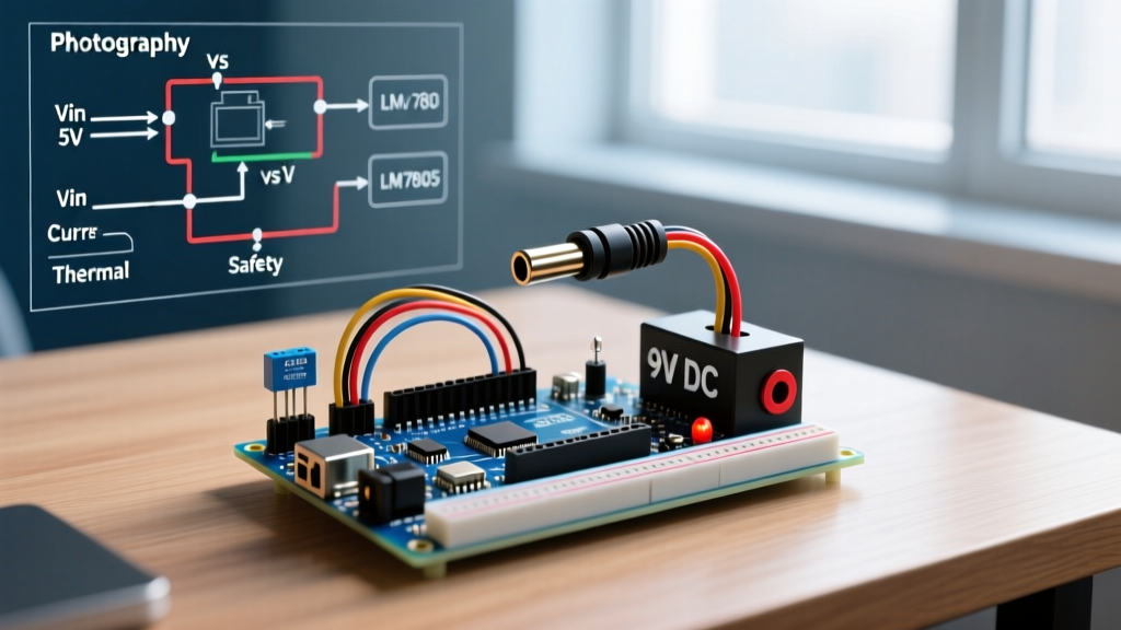
Both the Vin pin and the DC Barrel Jack feed directly into the board's onboard linear voltage regulator. On the Uno R3, this is typically the ON Semiconductor NCP1117ST50T3G. The barrel jack includes a 1N4007 diode in series to prevent damage if a center-negative adapter is mistakenly plugged in, resulting in a ~0.7V voltage drop before the regulator. According to the official Arduino Uno R3 Documentation, while the regulator can technically accept up to 20V, doing so will trigger immediate thermal shutdown.
The Thermal Bottleneck: Why 12V on Vin Fails
A common beginner mistake is purchasing a 12V DC wall adapter, plugging it into the barrel jack, and then attempting to power a 4-channel 5V relay module and a few servos from the Arduino's 5V pin. This almost always results in the board resetting randomly or the voltage regulator burning out.
To understand why, we must look at the physics of linear regulation. The NCP1117 drops excess voltage by converting it into heat. The SOT-223 package used on most Arduino clones and official boards has a junction-to-ambient thermal resistance ($\theta_{JA}$) of approximately 100°C/W, as detailed in the ON Semiconductor NCP1117 Datasheet.
The Power Dissipation Formula:
P_D = (V_IN - V_OUT) × I_LOAD
Example Scenario:
Input Voltage (V_IN) = 12V
Output Voltage (V_OUT) = 5V
Load Current (I_LOAD) = 300mA (0.3A)
P_D = (12V - 5V) × 0.3A = 2.1 Watts
A dissipation of 2.1W through a SOT-223 package without active cooling results in a temperature rise of roughly 210°C above ambient. Since the NCP1117 features internal thermal shutdown at ~155°C, the regulator will rapidly overheat, shut down to protect itself, cool slightly, turn back on, and repeat. This oscillation causes the 5V rail to collapse, resetting your microcontroller continuously. For a deeper dive into how these components manage heat, the SparkFun Voltage Regulator Tutorial provides excellent foundational thermal dynamics.
Best External Power Source Arduino Configurations
To avoid thermal throttling and ensure stable logic levels, you must match your external power architecture to your project's current draw. Here are the two industry-standard configurations used by professional prototypers.
Scenario A: High-Current 12V Systems (Motors, LED Strips, Relays)
If your project requires 12V for peripherals (like NEMA 17 stepper motors or high-power solenoids) but also needs 5V for the Arduino and sensors, never use the onboard linear regulator.
- Acquire a Buck Converter: Purchase an MP1584EN or LM2596 step-down module. In 2026, these switching regulators cost between $1.50 and $3.50 and boast efficiencies upwards of 92%.
- Wire the 12V Source: Connect your 12V DC supply to the input terminals of the buck converter and to your 12V peripherals (motor drivers, relay VCC).
- Step Down to 5V: Adjust the buck converter's potentiometer (or use a fixed 5V output variant) to output exactly 5.0V.
- Inject via the 5V Pin: Wire the 5V output of the buck converter directly to the Arduino's
5Vpin. Crucial: Ensure the USB cable is unplugged, or physically cut the 5V trace on the USB connector to prevent back-feeding your computer's USB port.
Scenario B: Portable Battery-Powered Sensors (Li-Ion / Li-Po)
For remote weather stations or wearable tech, a standard 9V alkaline battery is a poor choice due to its high internal resistance and rapid voltage sag. Instead, use a 3.7V 18650 Lithium-Ion cell or a Li-Po pouch.
- The Boost Converter Route: Use an MT3608 boost module to step the 3.7V - 4.2V Li-Ion voltage up to a stable 5V, feeding it into the
5Vpin. - The Power Bank Route: For projects drawing less than 100mA, standard USB power banks often enter "sleep mode" due to low current draw. Use a specialized "dummy load" USB stick (drawing ~50mA continuously) in parallel, or opt for a dedicated Li-Po UPS HAT featuring a TP4056 charging IC and a 5V boost circuit.
The Golden Rule: Common Grounding
The most frequent point of failure when integrating an external power source Arduino setup is neglecting the common ground. If you power a servo motor from an external 6V battery pack, and the Arduino from a USB cable, the PWM signal sent from the Arduino's digital pin will have no reference point. The signal will float, resulting in servo jitter or complete failure to respond.
Always connect the GND of your external power supply to one of the Arduino's GND pins. Voltage is a relative measurement; without a shared ground plane, the logic signals between the microcontroller and external modules are electrically meaningless.
Essential Protection Components
When wiring external power, especially inductive loads, implement these hardware safeguards:
- Flyback Diodes: Place a 1N4007 or 1N4148 diode in reverse bias across any relay coils or DC motors. When the magnetic field collapses, it generates a high-voltage spike that can arc across switch contacts or fry your microcontroller's GPIO pins.
- Optoisolators: For high-voltage AC switching or noisy industrial environments, use an optocoupler (like the PC817) to physically separate the external power ground from the Arduino ground, communicating only via light.
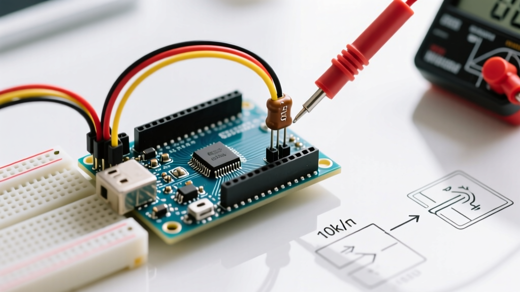
- Decoupling Capacitors: Place a 100μF electrolytic capacitor and a 0.1μF ceramic capacitor across the 5V and GND rails near high-draw ICs to smooth out transient voltage dips during switching events.
Summary Checklist for Safe Power Injection
Before energizing your next build, verify these parameters:
- Is the total 5V current draw under 300mA? If yes, the barrel jack/Vin is safe (use 7V-9V). If no, use an external buck converter to the 5V pin.
- Are all external power supply grounds tied to the Arduino GND?
- Are inductive loads protected with flyback diodes?
- If using the 5V pin, is the USB cable disconnected to prevent back-feeding?
By respecting the thermal limits of linear regulators and leveraging modern switching buck converters, you can ensure your microcontroller projects remain stable, efficient, and free from catastrophic power failures.