
The Prototyping Bottleneck: Why Spaghetti Wiring Fails
When developing CNC routers, camera sliders, or automated lab equipment, motion control is often the most time-consuming phase of prototyping. Wiring bare stepper drivers (like the A4988 or DRV8825) directly to a microcontroller via breadboards introduces severe workflow bottlenecks: loose Dupont connections cause missed steps, ground loops fry logic gates, and tracing pinouts wastes hours of debugging time. Integrating an Arduino stepper shield into your development workflow eliminates these hardware variables, allowing you to focus on kinematics and software logic.
As of 2026, the maker and engineering communities have largely moved past basic motor shields, favoring specialized stepper shields that offer UART tunability, advanced thermal dissipation, and modular driver sockets. This guide details a comprehensive workflow for selecting, wiring, thermally managing, and coding your Arduino stepper shield to cut prototyping time by up to 40%.
Shield Selection Matrix: Matching Hardware to Workflow
Choosing the wrong shield forces mid-project pivots. To optimize your workflow, match the shield architecture to your project's maturity phase. Below is a comparison of the three dominant Arduino stepper shield paradigms currently on the market.
| Shield Type | Driver IC Support | Interface | Approx. Cost (2026) | Best Workflow Phase |
|---|---|---|---|---|
| CNC Shield V3/V4 | A4988, DRV8825, TMC2208 | Direct Pin Mapping | $3.00 - $6.00 | Rapid Proof-of-Concept / GRBL Integration |
| Adafruit Motor Shield V2 | Custom I2C PWM IC | I2C (2 Pins) | $19.50 - $24.00 | Multi-motor robotics, I2C bus preservation |
| UART TMC2209 Shields | Trinamic TMC2209 | Step/Dir + UART | $14.00 - $22.00 | Precision instruments, silent operation, sensorless homing |
Workflow Tip: If your end goal is a custom PCB, start with a CNC Shield V3. Its direct pin mapping (e.g., Step on D2, Dir on D5 for X-axis) translates 1:1 to standard RAMPS/GRBL schematics, making the transition from shield to custom board seamless. For detailed pinout references and driver specifications, consult the Pololu A4988 Documentation and RepRap Stepper Driver Wiki.
Wiring Discipline: Eliminating Hardware Faults Early
An Arduino stepper shield is only as reliable as the connections feeding it. To maintain a fast iteration cycle, implement the following wiring standards on day one.
1. Motor Phase Identification
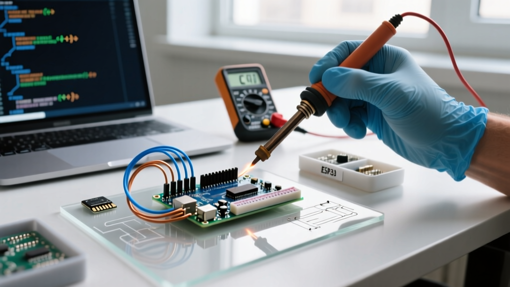
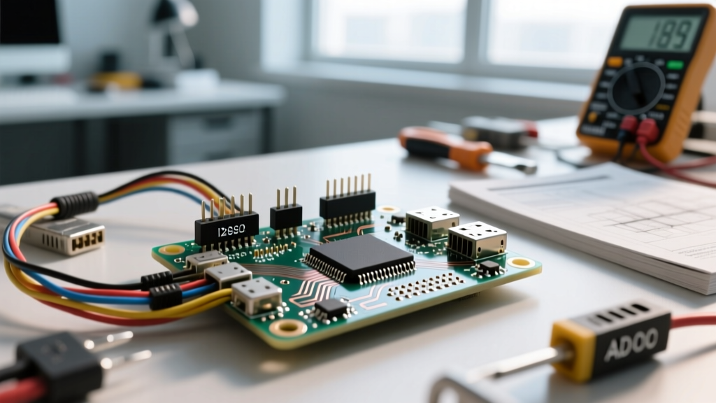
Misidentifying stepper coil pairs (A/A and B/B) results in severe vibration and zero rotation. Instead of relying on color codes—which vary wildly between manufacturers—use your multimeter. Set it to continuity mode and find the two pairs of wires that show a short circuit (typically 1 to 5 ohms). Tape them together in pairs before inserting them into the shield's terminal blocks.
2. Wire Gauge and Termination
For NEMA 17 motors drawing 1.0A to 1.5A per phase, 22 AWG to 24 AWG stranded wire is optimal. Avoid solid-core jumper wires for motor phases; the mechanical vibration of the shield's terminal blocks will fatigue and snap solid copper over time. Use ferrule crimps on stranded wires before seating them into the shield's screw terminals to prevent splaying and short circuits against adjacent Vref potentiometers.
Critical Warning: Never connect or disconnect stepper motors while the Arduino stepper shield is powered. The resulting inductive voltage spike will instantly destroy the driver IC's internal H-bridge, forcing you to halt your workflow and replace the chip.
The Vref Calibration Workflow: Preventing Thermal Throttling
Nothing derails a prototyping session faster than a stepper driver entering thermal shutdown mid-test. Calibrating the current limit (Vref) is a mandatory workflow step. However, in 2026, the approach depends heavily on your driver IC.
Legacy Drivers (A4988 / DRV8825)
These require physical trimpot tuning. The standard formula is Vref = Imax * 8 * Rsense.
For a standard A4988 with a 0.10Ω sense resistor and a 1.2A motor, your target Vref is 0.96V.
The Workflow: Power the shield via 12V/24V. Place your multimeter's black probe on the Arduino's GND pin and the red probe on the metal shaft of the driver's trimpot. Adjust with a ceramic screwdriver (metal shafts will short the pins to the logic rail).
The Counterfeit Chip Edge Case
A major hidden failure mode in modern supply chains is bootleg A4988 chips. These clones often use 0.05Ω sense resistors instead of 0.10Ω. If you apply the standard 0.96V Vref to a clone, you are actually pushing 2.4A through a 1.2A motor, leading to melted windings. Always verify the Rsense value printed on the SMD resistor marked 'R100' or 'R050' near the chip before calculating Vref.
Modern UART Drivers (TMC2209)
To truly optimize your workflow, migrate to UART-capable shields. The TMC2209 eliminates physical trimpots entirely. You set the RMS current via software commands (e.g., driver.rms_current(1200); using the TMCStepper library). This allows you to tweak thermal limits and microstepping on the fly without grabbing a multimeter, drastically accelerating the testing phase.
Software Workflow: Non-Blocking Motion Control
Using delay() or blocking for() loops to generate step pulses is a novice mistake that paralyzes your ability to integrate sensors, buttons, or serial communication later. An optimized Arduino stepper shield workflow mandates non-blocking code architecture from the very first sketch.
AccelStepper vs. Hardware Timers
The AccelStepper Library remains the gold standard for non-blocking kinematics. By calling stepper.run() inside your main loop(), the library handles the complex acceleration ramps and step timing in the background.
Optimized Loop Pattern:
void loop() {
  // 1. Poll sensors and serial inputs (Non-blocking)
  handleSerialCommands();
  checkLimitSwitches();

  // 2. Update motion profiles
  stepperX.run();
  stepperY.run();

  // 3. Handle auxiliary tasks
  updateDisplay();
}
For advanced users requiring perfectly synchronized multi-axis movement (like plotting or CNC), relying on software timers like AccelStepper can introduce microsecond jitters. In these cases, utilize shields that support hardware timer interrupts or migrate to an ESP32-based shield setup utilizing the StepControl library, which leverages hardware timers for jitter-free pulse generation up to 300,000 steps per second.
Transitioning from Shield to Custom PCB
An Arduino stepper shield is a prototyping tool, not always a production solution. Recognizing when to abandon the shield is a crucial workflow milestone. Plan to design a custom PCB when:
- Form Factor Constraints: The shield stack exceeds your enclosure's Z-height.
- Current Demands: You need to drive NEMA 23 or NEMA 34 motors requiring 4A+ per phase, which exceeds the trace width and thermal capacity of standard 1oz copper Arduino shields.
- Unit Cost: Your production run exceeds 50 units, and the $4-$20 cost of a shield destroys your margin compared to a $1.50 bare IC implementation.
Frequently Asked Questions
Why is my stepper motor getting too hot to touch on the shield?
Stepper motors are designed to run hot; a surface temperature of 60°C to 80°C (140°F to 176°F) is normal for NEMA 17 motors at rated current. However, if it smells like burning insulation or exceeds 90°C, your Vref is too high, or you are running 100% holding current while stationary. Implement a software-based 'idle current reduction' (available natively in TMC2209 UART configurations) to drop holding torque by 50% when the motor is not moving.
Can I power the Arduino and the Stepper Shield from the same 12V supply?
Yes, but with a caveat. Most CNC shields feature a jumper (often labeled V-IN or 5V) that routes the main motor power supply through the Arduino's onboard linear voltage regulator. If you supply 24V to the shield for better high-speed stepper torque, you must remove this jumper, or you will instantly vaporize the Arduino's 5V regulator. Always power the Arduino via USB or its dedicated DC barrel jack when using motor supplies above 12V.
How do I prevent ground loops when using limit switches with the shield?
Stepper motors generate massive electromagnetic interference (EMI) during commutation. If your limit switches share a ground return path with the motor phases, voltage spikes will trigger false switch readings in your code. Optimize your wiring by using shielded cables for limit switches, grounding the shield mesh at the Arduino end only, and utilizing the shield's dedicated opto-isolated logic pins if available.