
Why Your Arduino Needs an External Power Supply Module
When prototyping with microcontrollers, beginners often rely on the Arduino Uno's onboard 5V and 3.3V pins to power sensors, displays, and actuators. However, this approach quickly hits a physical wall. The USB port limits you to roughly 500mA, while the onboard NCP1117 linear regulator (fed via the barrel jack or Vin pin) can technically supply up to 1A but is severely constrained by thermal dissipation. If you attempt to power a strip of WS2812B LEDs or a pair of MG996R servos directly from the Arduino's 5V pin, you risk triggering thermal shutdown, browning out the ATmega328P, or permanently damaging the board's PCB traces.
The solution is integrating an external power supply module for Arduino circuits. By offloading high-current demands to dedicated switching regulators or specialized breadboard modules, you protect your microcontroller while ensuring stable logic levels. In this 2026 guide, we will break down the two most ubiquitous modules in the maker space—the MB102 breadboard power supply and the LM2596 DC-DC buck converter—and provide exact wiring schematics, thermal calculations, and troubleshooting frameworks.
The Physics of Arduino Power Limits
Before wiring any module, you must understand why external power is necessary. According to the Arduino Official Power Supplies Guide, the onboard linear regulator drops excess voltage as heat. The power dissipated ($P_d$) is calculated as:
Pd = (Vin - Vout) × Iload
If you feed 12V into the Vin pin and draw 300mA from the 5V pin, the regulator must dissipate (12V - 5V) × 0.3A = 2.1 Watts. Without a massive heatsink, the SOT-223 package will exceed its 165°C junction temperature and shut down. External power supply modules bypass this bottleneck by using switching topologies that achieve 85-95% efficiency, generating a fraction of the heat.
Choosing the Right Power Supply Module
1. The MB102 Breadboard Module (For Low-Current Prototyping)
Priced between $2.00 and $4.00, the MB102 is a staple for breadboard prototyping. It accepts 6.5V to 12V via a standard 5.5x2.1mm barrel jack or 5V via USB, and uses two AMS1117 linear dropout (LDO) regulators to provide selectable 3.3V and 5V rails via jumper caps.
- Max Practical Current: 300mA continuous per rail (limited by SOT-223 thermal throttling).
- Best For: I2C sensors, small OLED displays, ESP8266 modules, and logic-level shifters.
- Failure Mode: Supplying 12V while drawing near-max current will cause the AMS1117 to overheat. Keep the input voltage between 7V and 9V for optimal thermal performance.
2. The LM2596 DC-DC Buck Converter (For High-Current Actuators)
For driving stepper motors, DC motors, high-power LED arrays, or long servo chains, the LM2596 step-down module ($3.00 to $6.00) is the industry standard. As detailed in the Texas Instruments LM2596 Product Page, this switching regulator operates at 150kHz, allowing for smaller filter components and high efficiency.
- Input Voltage: 4.5V to 40V DC.
- Output Voltage: 1.23V to 37V (adjustable via onboard trimpot).
- Max Practical Current: 2A continuous (3A peak) without active cooling.
- Best For: NEMA 17 steppers, MG996R servos, automotive 12V-to-5V step-down applications.
Specification Comparison Matrix
| Feature | Arduino Onboard 5V | MB102 Breadboard Module | LM2596 Buck Converter |
|---|---|---|---|
| Topology | Linear (NCP1117) | Linear (AMS1117) | Switching (Buck) |
| Efficiency | ~35% (at 12V in) | ~40% (at 9V in) | 85% - 95% |
| Max Continuous Current | ~500mA (USB dependent) | ~300mA (per rail) | ~2.0A (with heatsink) |
| Adjustability | Fixed 5V / 3.3V | Jumper Select (5V / 3.3V) | Fully Adjustable (Trimpot) |
| Output Ripple | Extremely Low | Extremely Low | Moderate (requires LC filtering for ADC) |
Step-by-Step: Wiring the LM2596 for Motors and Servos
The most common mistake makers make when using an external power supply module for Arduino projects is failing to establish a common ground. Without a shared ground reference, the PWM signals from the Arduino will "float" relative to the motor driver, resulting in erratic behavior or destroyed GPIO pins.
- Set the Output Voltage First: Before connecting anything to your Arduino or load, power the LM2596 input terminals with your DC source (e.g., a 12V 5A laptop brick). Connect a digital multimeter to the output terminals. Use a small Phillips screwdriver to turn the blue trimpot until the multimeter reads exactly 5.00V (or your required logic voltage).
- Wire the Power Rails: Connect the LM2596 VOUT+ to the breadboard's positive rail (or directly to the servo's VCC wire). Connect VOUT- to the breadboard's negative rail.
- Establish Common Ground (Critical): Run a jumper wire from the LM2596 VOUT- terminal directly to one of the Arduino's GND pins. Do not skip this step. For high-current inductive loads, use a thick (18 AWG) wire for the ground return path to prevent ground bounce.
- Connect the Signal Wires: Wire your Arduino PWM pins (e.g., Pin 9, 10) to the signal input of your servos or motor driver. Because the grounds are shared, the Arduino's 5V logic HIGH will be correctly interpreted by the external components.
Step-by-Step: Wiring the MB102 for Sensor Prototyping
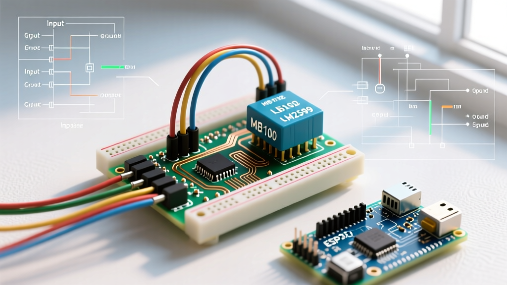
The MB102 is designed to plug directly into the dual power rails of a standard 830-point solderless breadboard.
- Seat the Module: Align the MB102 pins with the breadboard's power holes. Ensure the notch on the module aligns with the center groove of the breadboard.
- Configure Jumpers: Place the black jumper caps on the pins marked "5V" for both the red and blue rail groups. (If using an ESP32, set one side to 3.3V).
- Provide Input Power: Plug a 7.5V or 9V DC center-positive wall adapter into the barrel jack. Alternatively, use a USB-A to Mini-USB cable to feed 5V directly, bypassing the internal 5V LDO entirely (which runs much cooler).
- Bridge to Arduino: Use male-to-male jumper wires to connect the breadboard's 5V rail to the Arduino's 5V pin, and the breadboard's GND rail to the Arduino's GND. Note: Only do this if the Arduino is powered via USB. If the Arduino is powered via its own barrel jack, do not tie the 5V rails together, only tie the GNDs.
Crucial Troubleshooting: Avoiding Common Failure Modes
The "Fake" LM2596 Chip Epidemic
As documented in various teardowns by the electronics community and referenced in SparkFun's Power Supply Tutorials, the market is flooded with counterfeit LM2596 modules. Unscrupulous manufacturers often solder an LM2576 chip (which switches at 52kHz) onto a PCB designed for the 150kHz LM2596. Because the 52kHz chip requires a much larger inductor (typically 100µH vs the 33µH provided on the board), the module suffers from massive ripple current, severe overheating, and premature failure at loads above 1A. How to verify: If your module's inductor is unusually small and the chip gets blisteringly hot at just 1A of draw, you likely have a fake. Purchase modules from reputable distributors like Digi-Key or Mouser, or look for modules featuring the larger, correct 33µH toroidal inductors and Schottky diodes (like the 1N5822).
Arduino Reset Loops and Brownouts
If your Arduino randomly resets when a motor engages, you are experiencing a voltage sag (brownout). Even with an external power supply module, the transient current spike of a motor starting can pull the shared 5V rail down below the ATmega328P's brownout detection threshold (typically 4.3V). The Fix: Add a large electrolytic capacitor (470µF to 1000µF, rated for at least 10V) across the 5V and GND rails as close to the motor driver as possible. This acts as a local energy reservoir to absorb transient spikes without dragging down the main bus voltage.
ADC Noise from Switching Regulators
The LM2596 generates high-frequency switching noise (150kHz ripple) on its output. If you are using the Arduino's analog pins (A0-A5) to read precision sensors like load cells or thermistors, this noise will manifest as jitter in your analogRead() values. The Fix: Insert a simple LC low-pass filter between the LM2596 output and your analog sensor's VCC pin. A 10Ω resistor in series with the VCC line, followed by a 10µF ceramic capacitor to ground, will drastically attenuate the switching ripple and stabilize your ADC readings.
Summary
Integrating a dedicated power supply module for Arduino projects is not just a best practice; it is a requirement for any circuit drawing more than a few hundred milliamps. By understanding the thermal limitations of linear regulators like the MB102's AMS1117, and the wiring nuances of switching buck converters like the LM2596, you can build robust, crash-proof prototypes. Always remember the golden rule of mixed-voltage systems: share the ground, respect the current limits, and verify with a multimeter before applying power.