
Introduction to Arduino Limit Switch Compatibility
Integrating an Arduino limit switch into a CNC router, 3D printer, or robotic arm seems trivial until you encounter phantom triggers, melted contacts, or logic-level mismatches. As of 2026, the maker ecosystem has heavily shifted toward 3.3V logic boards like the Arduino Uno R4 Minima and ESP32-S3, making legacy 5V and 24V industrial sensor compatibility a critical hurdle. This guide provides a deep-dive compatibility matrix, electrical interfacing rules, and failure-mode analysis to ensure your limit switches operate flawlessly in high-EMI environments.
Technology Matrix: Mechanical, Optical, Magnetic, and Inductive
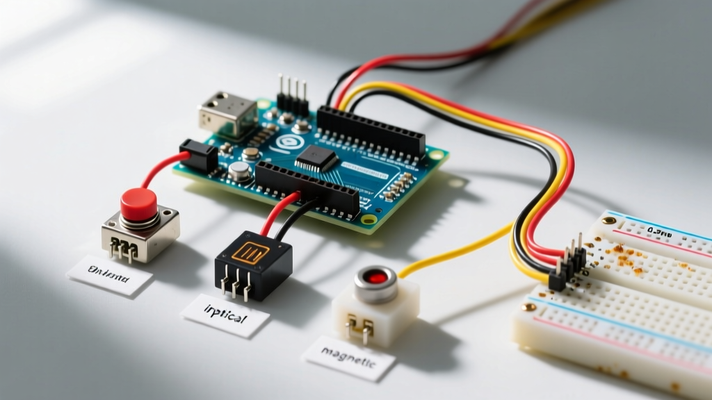
Not all limit switches are created equal. The physical operating environment dictates which switch technology is compatible with your microcontroller's input pins. Below is a compatibility and application matrix for the four primary switch types used in maker and light-industrial projects.
| Switch Type | Typical Models | Operating Voltage | Arduino Direct Compatibility | Best Use Case |
|---|---|---|---|---|
| Mechanical (Microswitch) | Omron D2F-01F, Honeywell V15 | 5V - 250V AC/DC | Yes (Requires Pull-up/Down) | 3D printer endstops, low-speed CNC |
| Optical (Photoelectric) | Generic IR Slot Sensors | 3.3V - 5V DC | Yes (Direct Logic Output) | High-speed encoders, dust-free environments |
| Magnetic (Hall Effect) | A3144, DRV5053 | 3.3V - 24V DC | Yes (Check VCC tolerance) | Wet environments, non-contact linear limits |
| Inductive (Proximity) | LJ12A3-4-Z/BX | 10V - 30V DC | No (Requires Optocoupler/Divider) | Heavy CNC mills, metallic target detection |
Logic Level Matching: 5V vs. 3.3V Microcontrollers
The most common cause of fried microcontrollers in limit switch circuits is ignoring logic level thresholds. A standard Arduino Uno (ATmega328P) operates at 5V logic, meaning it expects a HIGH signal to be at least 3.0V (0.6 × VCC). However, modern boards like the Arduino Nano 33 IoT or ESP32 operate at 3.3V. Feeding a 5V signal from an older optical limit switch module directly into a 3.3V ESP32 GPIO pin will degrade the silicon over time or cause immediate latch-up.
The Pull-Up/Pull-Down Resistor Dilemma
Mechanical switches require a defined logic state when open. While the Arduino's internal pull-up resistors (typically 20kΩ to 50kΩ) are convenient, they are highly susceptible to electromagnetic interference (EMI) in environments with stepper motors or spindle routers.
- Internal Pull-ups: Use only for short wire runs (<10cm) in low-noise environments. Activate via
pinMode(pin, INPUT_PULLUP);as detailed in the official Arduino InputPullup documentation. - External Pull-ups (4.7kΩ): Mandatory for wire runs exceeding 30cm. A 4.7kΩ resistor provides a much stiffer voltage bias, effectively shorting out induced noise from adjacent motor cables.
- Pull-down Configurations: If your switch must pull the line HIGH when triggered (e.g., interfacing with certain PLC emulation shields), use a 10kΩ pull-down resistor to GND. Note that internal pull-downs are only available on specific architectures like the ESP32, not standard AVR Arduinos.
Industrial Sensors: Interfacing 12V/24V with Arduino
When building heavy-duty CNC machines, makers frequently upgrade to inductive proximity sensors like the LJ12A3-4-Z/BX (typically $4.00 to $8.00 per unit). These sensors operate on 12V or 24V and output a corresponding high voltage when a metal target is detected. Connecting this directly to a 5V Arduino will destroy the ATmega chip instantly.
NPN vs. PNP Output Configurations
Industrial sensors come in NPN (sinking) and PNP (sourcing) variants. Understanding this is critical for Arduino compatibility:
- NPN (Sinking): The output pulls to GND when triggered. You must wire the sensor's output to the Arduino pin through an optocoupler (like the PC817, ~$0.20) or a voltage divider. The Arduino pin requires a pull-up resistor to its own 5V or 3.3V VCC.
- PNP (Sourcing): The output supplies VCC (12V/24V) when triggered. You must use a voltage divider (e.g., 10kΩ and 2.2kΩ) to step the 24V down to a safe ~4.3V for a 5V Arduino, or use an optocoupler with a current-limiting resistor on the LED side.
Expert Insight: Always use an optocoupler (e.g., PC817 or 6N137 for high-speed) when interfacing 24V industrial limit switches with an Arduino. This provides galvanic isolation, completely eliminating ground loops that occur when the Arduino shares a power supply with high-current spindle motors.
Hardware vs. Software Debouncing Strategies
Mechanical switches suffer from contact bounce—a phenomenon where the metal contacts physically chatter for 1 to 5 milliseconds before settling. If your Arduino polls the pin during this window, a single limit trigger will register as dozens of rapid presses, causing your CNC router to lose its coordinate origin.
Hardware RC Filtering
For mission-critical limits where software latency is unacceptable, implement a hardware RC (Resistor-Capacitor) low-pass filter. Place a 100nF ceramic capacitor (X7R dielectric) in parallel with the switch, and a 10kΩ resistor in series with the signal line. This creates a time constant ($\tau = R \times C$) of 1 millisecond. The capacitor absorbs the high-frequency bounce spikes, while the X7R dielectric ensures the capacitance remains stable across varying ambient temperatures, unlike cheaper Y5V capacitors which lose up to 50% capacitance when heated.
Software Debouncing
If hardware space is constrained, rely on software debouncing. The standard Arduino Debounce example uses millis() to ignore state changes for 50ms. However, for complex state machines, we highly recommend the Bounce2 library. It handles debouncing non-blockingly and provides edge-detection methods like fell() and rose(), which are vastly superior for triggering hardware interrupts without writing convoluted flag logic.
Common Failure Modes and Edge Cases
Even with perfect wiring, limit switches fail in the field. Recognizing these edge cases separates amateur builds from reliable machinery.
Contact Welding and Current Overload
A common mistake is using a microswitch to directly drive a relay coil or a solenoid lock. Generic microswitches (often $0.10 each) are rated for logic-level currents. Switching inductive loads without a flyback diode causes an arc that will weld the silver-alloy contacts shut after a few dozen cycles. If your limit switch must trigger a high-current load, use it to switch a logic-level MOSFET (like the IRLZ44N) or a solid-state relay instead. For low-current logic applications, upgrading to a switch with gold-flash contacts, such as the Omron D2F series ($1.50 - $2.50), prevents oxidation and ensures reliable continuity in dry circuits.
EMI and Ground Loops in Motorized Systems
When a stepper motor driver (like the TB6600 or DM542) switches high currents, it injects massive voltage spikes into the shared ground plane. If your Arduino and limit switches share this ground without star-topology wiring, the ground potential can fluctuate by several volts. The Arduino will misinterpret this ground bounce as a limit switch trigger. The Fix: Implement a star-ground topology where the Arduino's GND, the motor driver's logic GND, and the limit switch pull-down GND all meet at a single, centralized physical point. Furthermore, route limit switch cables in separate conduit or at least 5cm away from stepper motor phase wires.
Optical Sensor Ambient Light Interference
Optical limit switches (IR slot sensors) are highly susceptible to ambient sunlight or high-intensity workshop LEDs, which can contain infrared spectrum leakage. If your 3D printer occasionally fails to home its Z-axis when placed near a window, the IR receiver is likely being saturated. Shield the sensor with heat-shrink tubing or switch to a modulated IR receiver paired with a 38kHz pulsed IR LED to reject ambient DC light sources.
Summary Checklist for Deployment
- Verify Logic Levels: Match sensor VCC and output voltage to your specific board (5V AVR vs. 3.3V ARM/ESP).
- Stiffen Pull-ups: Add external 4.7kΩ resistors for any switch wire longer than 10cm.
- Isolate High Voltage: Use PC817 optocouplers for any inductive sensor operating above 5V.
- Filter the Bounce: Use 100nF X7R capacitors for hardware debouncing on critical emergency stops and home limits.
- Protect Contacts: Never switch inductive loads directly through mechanical microswitch contacts.