
Demystifying the Black Box: How Does an Arduino Work?
When makers first start building circuits, the microcontroller often feels like a magic black box. You write code, hit upload, and the board executes your commands. But when a sketch fails to compile, a sensor returns garbage data, or a pin refuses to toggle, guessing is no longer an effective strategy. To truly master hardware debugging, you must understand how does an Arduino work at the silicon level. By dissecting the internal architecture of the classic ATmega328P-based boards, we can map internal hardware mechanisms directly to real-world troubleshooting workflows.
While the maker ecosystem has evolved significantly by 2026 with advanced ARM and RISC-V architectures entering the fray, the foundational AVR architecture of the Arduino Uno remains the industry standard for learning bare-metal hardware troubleshooting. Below, we break down the core subsystems of the Arduino and provide actionable fixes for the most common failure modes.
1. The Bootloader and Execution Sequence
At the heart of the Arduino's user-friendly upload process is the bootloader—a small program (typically Optiboot, occupying just 512 bytes) pre-flashed into a dedicated, write-protected section of the microcontroller's flash memory. When the board resets, the bootloader runs first. It listens to the hardware serial UART (pins 0 and 1) for a specific baud rate handshake from the Arduino IDE. If it detects the upload sequence, it writes the new sketch to memory; if not, after a brief timeout (usually around 500ms), it jumps to the start of your user sketch.
Expert Troubleshooting Tip: If you encounter the dreaded avrdude: stk500_getsync() attempt 10 of 10: not in sync: resp=0x00 error, the issue is almost always a failure in the auto-reset circuit. The Arduino IDE relies on a 100nF capacitor connected between the DTR line of the USB-to-Serial chip (ATmega16U2) and the RESET pin of the main MCU. If this capacitor is damaged, or if you are using a clone board with a missing trace, manual reset timing is required: hold the physical RESET button, click Upload in the IDE, and release the button exactly when the console shows "Uploading...".
2. GPIO Architecture and Register Mapping
General Purpose Input/Output (GPIO) pins are not just simple wires; they are controlled by internal hardware registers. On the ATmega328P, pins are grouped into three ports: PORTB, PORTC, and PORTD. Each port relies on three specific registers to function:
- DDRx (Data Direction Register): Dictates whether a pin is an INPUT (0) or OUTPUT (1).
- PORTx (Data Register): Sets the pin HIGH (1) or LOW (0) when configured as an output, or enables the internal pull-up resistor when configured as an input.
- PINx (Input Pins Register): Reads the actual physical voltage state of the pin.
Understanding this register-level operation is critical when diagnosing "dead" pins. If a pin outputs a constant 2.5V instead of a clean 0V or 5V, the internal CMOS push-pull transistors have likely been damaged by excessive current draw or voltage back-feeding.
| Parameter | Safe Operating Limit | Absolute Maximum | Common Failure Consequence |
|---|---|---|---|
| DC Current per I/O Pin | 20 mA | 40 mA | Silicon degradation, permanent HIGH/LOW latch |
| Total VCC/GND Current | 150 mA | 200 mA | Internal bond wire melting, total MCU death |
| Input Voltage (Any Pin) | -0.5V to 5.5V | VCC + 0.5V | Parasitic diode conduction, latch-up effect |
Source: Microchip ATmega328P Product Specifications
3. Analog-to-Digital Conversion (ADC) Dynamics
When you call analogRead(), the Arduino utilizes an internal 10-bit Successive Approximation Register (SAR) ADC. It maps the 0-5V range into 1024 discrete steps (yielding a resolution of roughly 4.88mV per step). However, the ADC does not measure voltage instantaneously. It uses an internal sample-and-hold capacitor (approx. 14pF) that must physically charge to the input voltage level before the conversion begins.
The High-Impedance Bug: A highly specific and frequently misunderstood issue occurs when reading sensors with high output impedance (greater than 10kΩ). If the source cannot supply enough current to charge the 14pF internal capacitor within the ADC's sampling window (typically 1.5 to 13 ADC clock cycles), the read value will be inaccurate, often pulling toward the previously sampled pin's voltage due to internal multiplexer crosstalk.
- The Fix: If you must use a high-impedance sensor (like a specific photoresistor voltage divider or a high-value thermistor), place a 100nF ceramic decoupling capacitor directly between the analog input pin and GND. This external capacitor acts as a local charge reservoir, instantly filling the ADC's internal sampling capacitor and eliminating noisy or floating reads.
4. Power Delivery and Brownout Detection
Understanding how power flows through the board is vital for diagnosing random reboots. When powered via the barrel jack or VIN pin, the Arduino relies on an onboard Linear Dropout Regulator (LDO), typically the NCP1117-5.0. This component burns off excess voltage as heat to maintain a stable 5V rail. Furthermore, the ATmega328P features an internal Brownout Detector (BOD) usually set to trigger at 2.7V or 4.3V. If the 5V rail dips below this threshold for even a microsecond, the MCU forces a hard reset to prevent memory corruption.
Master Diagnostic Matrix: Symptoms to Silicon Fixes
Use this structured matrix to bypass guesswork and target the exact hardware subsystem causing your failure. For deeper community and official debugging steps, refer to the Official Arduino Troubleshooting Guide.
| Observed Symptom | Internal Subsystem | Root Cause & Actionable Fix |
|---|---|---|
| Board gets excessively hot near the power jack | NCP1117 LDO | Cause: Input voltage > 9V with high current draw causing thermal shutdown. Fix: Bypass the LDO; power the 5V pin directly with a clean 5V buck converter. |
| Random resets when a relay or motor activates | BOD & Power Rail | Cause: Inductive kickback or voltage sag tripping the Brownout Detector. Fix: Add flyback diodes to inductive loads and separate motor power from the logic 5V rail. |
| Pin 13 LED glows dimly or analog reads are erratic | USB-to-Serial / SPI Bus | Cause: Pin 13 is tied to the SPI SCK line and the onboard LED. High-frequency SPI traffic or missing pull-downs cause ghost voltages. Fix: Avoid using Pin 13 for sensitive inputs; use Pins 2-12 for critical logic. |
| Sketch uploads successfully but immediately restarts | Watchdog Timer / Memory | Cause: Stack overflow corrupting the return address, or an infinite Watchdog Timer loop without a reset. Fix: Check for recursive functions, reduce large local arrays, and verify WDT configuration. |
Advanced Hardware Verification Steps
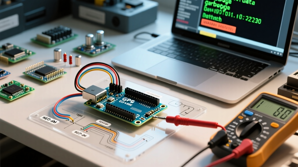
If you have applied the fixes above and the board remains unresponsive, it is time to verify the hardware integrity of the Arduino Uno Rev3 architecture using a multimeter.
- Verify the 5V and 3.3V Rails: Set your multimeter to DC voltage. Probe the 5V pin and GND. You should read between 4.8V and 5.1V. Probe the 3.3V pin; it should read exactly 3.3V (sourced from the ATmega16U2 internal regulator on official boards). If 5V reads 0V, check the polyfuse (a small green component near the USB port) for continuity.
- Check the Crystal Oscillator: The ATmega328P relies on a 16MHz ceramic resonator. If this component cracks or fails, the MCU cannot generate clock cycles, resulting in a "bricked" state with no serial output. Use an oscilloscope to probe the XTAL1 pin; you should see a clean 16MHz square wave.
- Isolate the USB-to-Serial Chip: If the IDE cannot find the COM port, the ATmega16U2 chip may be corrupted. You can recover it by flashing the official Arduino Uno Rev3 DFU firmware using an external ISP programmer (like a USBasp) connected to the 6-pin ICSP header nearest to the USB port.
Ultimately, asking how does an Arduino work is the first step toward transitioning from a hobbyist who copies code to an embedded engineer who designs robust, fault-tolerant systems. By respecting the electrical limits of the GPIO registers, understanding the physical realities of the ADC sampling capacitor, and managing power delivery thermals, you will eliminate 95% of the hardware bugs that plague maker projects.