
Introduction to the DS3231 Real-Time Clock
When building data loggers, automated greenhouse controllers, or time-based relays, precise timekeeping is non-negotiable. The Arduino RTC DS3231 configuration is the gold standard for hobbyists and engineers alike. Unlike its predecessor, the DS1307, which relies on an external crystal oscillator that drifts heavily with temperature changes, the DS3231 features an integrated Temperature-Compensated Crystal Oscillator (TCXO). This guarantees an accuracy of ±2ppm (parts per million) from 0°C to +40°C, translating to a maximum drift of roughly one minute per year.
As of 2026, the maker market offers dozens of breakout boards featuring the DS3231 chip (now manufactured by Analog Devices after their acquisition of Maxim Integrated). However, not all modules are created equal. This guide covers the exact hardware selection, I2C wiring matrices, software configuration, and critical safety modifications required to deploy the DS3231 reliably in your microcontroller projects.
Hardware Selection and the ZS-042 Battery Hazard
Before writing a single line of code, you must evaluate the physical breakout board you are using. The market is currently dominated by three main variants:
| Module Variant | Approx. Price | Battery Type | Build Quality & Notes |
|---|---|---|---|
| Generic ZS-042 | $1.50 - $2.50 | LIR2032 (Rechargeable) | Includes AT24C32 EEPROM. Requires safety modification. |
| Adafruit 3013 | $9.50 - $11.00 | CR1220 (Non-rechargeable) | Excellent build, includes proper level shifting and safe battery circuit. |
| SparkFun BOB-12708 | $14.50 - $16.00 | CR2032 (Non-rechargeable) | Robust, designed for 3.3V and 5V logic systems safely. |
Critical Safety Warning: The ZS-042 Charging Circuit
WARNING: If you purchased a cheap generic ZS-042 module, it likely includes a charging circuit designed for an LIR2032 lithium-ion coin cell. This circuit consists of a 1N4148 diode and a 200Ω resistor. If you power the module with 5V and insert a standard, non-rechargeable CR2032 battery, the circuit will attempt to charge it, leading to battery swelling, thermal runaway, or explosion.
The Fix: Either use a proper LIR2032 battery, or physically desolder/remove the 1N4148 diode or the 200Ω resistor near the battery holder and use a standard CR2032.
I2C Wiring Matrix for Popular Microcontrollers
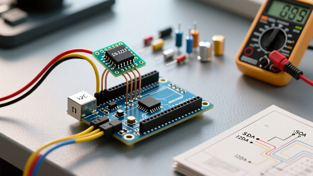
The DS3231 communicates via the I2C protocol. The primary I2C address for the RTC chip is 0x68. If your module includes the AT24C32 EEPROM (common on the ZS-042), it resides at address 0x57. Below is the wiring matrix for connecting the module to popular development boards.
| DS3231 Pin | Arduino Uno / Nano | Arduino Mega 2560 | ESP32 (Standard) | Raspberry Pi Pico |
|---|---|---|---|---|
| VCC | 5V | 5V | 3.3V | 3.3V |
| GND | GND | GND | GND | GND |
| SDA (Data) | A4 | 20 | GPIO 21 | GP4 |
| SCL (Clock) | A5 | 21 | GPIO 22 | GP5 |
| SQW/INT | D2 or D3 (Interrupt) | D2 or D3 | Any GPIO | Any GP |
Note: The ZS-042 module includes 4.7kΩ pull-up resistors on the SDA and SCL lines. If you are chaining multiple I2C devices and experience bus lockups, you may need to remove these resistors to prevent the total pull-up resistance from dropping too low.
Software Configuration: Installing RTClib
While you can write raw I2C register commands using the Wire library, the most efficient way to handle time parsing, leap year calculations, and Unix timestamps is via the Adafruit RTClib. It is actively maintained and handles the heavy lifting of BCD (Binary-Coded Decimal) to decimal conversion.
- Open the Arduino IDE and navigate to Sketch > Include Library > Manage Libraries.
- Search for RTClib by Adafruit and install the latest version.
- When prompted, agree to install any missing dependencies (such as the Adafruit BusIO library).
Core Code Implementation
Below is a robust configuration sketch. It checks if the RTC has lost power (e.g., dead coin cell battery) and automatically sets the time to the compilation timestamp. It then continuously outputs the formatted time and Unix timestamp to the Serial Monitor.
#include <Wire.h>
#include <RTClib.h>

RTC_DS3231 rtc;

void setup () {
  Serial.begin(115200);
  // Wait for serial port to connect. Needed for native USB boards (Leonardo, ESP32)
  while (!Serial);

  if (!rtc.begin()) {
    Serial.println("Couldn't find RTC. Check I2C wiring.");
    Serial.flush();
    while (1) delay(10); // Halt execution
  }

  // Check if the RTC lost power and reset to default
  if (rtc.lostPower()) {
    Serial.println("RTC lost power, let's set the time!");
    // Set to compile time. For manual setting use:
    // rtc.adjust(DateTime(2026, 1, 15, 12, 30, 0));
    rtc.adjust(DateTime(F(__DATE__), F(__TIME__)));
  }
}

void loop () {
  DateTime now = rtc.now();

  Serial.print(now.year(), DEC);
  Serial.print('/');
  Serial.print(now.month(), DEC);
  Serial.print('/');
  Serial.print(now.day(), DEC);
  Serial.print(" ");
  Serial.print(now.hour(), DEC);
  Serial.print(':');
  Serial.print(now.minute(), DEC);
  Serial.print(':');
  Serial.print(now.second(), DEC);
  Serial.println();

  Serial.print("Unix Timestamp: ");
  Serial.println(now.unixtime());

  delay(1000);
}
Advanced Configuration: Alarms and the SQW Pin
One of the most powerful features of the DS3231 is its ability to wake a microcontroller from deep sleep using hardware interrupts. This is essential for battery-powered IoT nodes. The DS3231 features two alarms: Alarm 1 (can trigger on seconds, minutes, hours, or days) and Alarm 2 (can trigger on minutes, hours, or days).
Configuring Alarm 1 for Deep Sleep Wakeup
To use the SQW/INT pin as an interrupt trigger rather than a square wave clock output, you must configure the RTC's control register (0x0E). RTClib abstracts this process beautifully.
// In setup(), after rtc.begin():
// Disable square wave output, enable alarm interrupts
rtc.writeSqwPinMode(DS3231_OFF);

// Set Alarm 1 to trigger at exactly 30 seconds past the minute
rtc.setAlarm1(rtc.now() + TimeSpan(30), DS3231_A1_Second);

// Attach interrupt to Arduino Pin 2 (INT0)
pinMode(2, INPUT_PULLUP);
attachInterrupt(digitalPinToInterrupt(2), wakeUp_ISR, FALLING);
Important: Inside your Interrupt Service Routine (ISR), you must clear the alarm flag, or the SQW pin will remain pulled LOW indefinitely, causing immediate re-triggering. Use rtc.clearAlarm(1); in your main loop after waking up.
Troubleshooting Edge Cases and Failure Modes
Even with perfect wiring, I2C communication can be temperamental. Here are the most common failure modes encountered when configuring the Arduino RTC DS3231 and how to resolve them based on the official Arduino Wire specifications.
1. The 'Stuck in Setup' Infinite Loop
Symptom: The serial monitor prints "Couldn't find RTC" and halts, or the microcontroller fails to boot entirely.
Cause: Missing pull-up resistors on the I2C lines, or a bus lockup caused by a previous brownout where the SDA line was left LOW.
Solution: Measure the voltage on SDA and SCL with a multimeter; both should read close to VCC (5V or 3.3V). If they read near 0V, your pull-ups are missing or the bus is locked. Power cycle the module completely (disconnect VCC and the coin battery for 60 seconds to drain the capacitors and reset the I2C state machine).
2. Time Drifting by Exactly 1 Hour
Symptom: The RTC keeps perfect time, but is offset by exactly 3600 seconds.
Cause: Daylight Saving Time (DST) logic. The DS3231 hardware does not understand time zones or DST; it only tracks raw UTC/local time based on what you feed it.
Solution: Handle DST in your application code, or sync the RTC periodically via NTP (Network Time Protocol) if your project includes an ESP32 or Ethernet shield.
3. AT24C32 EEPROM I2C Address Conflicts
Symptom: You are using an I2C scanner and see addresses 0x57 and 0x68, but writing to 0x57 fails or corrupts data.
Cause: The AT24C32 EEPROM on the ZS-042 module has address pins (A0, A1, A2) tied to ground by default, making its address 0x57. If you have multiple ZS-042 modules on the same bus, their EEPROMs will collide.
Solution: Solder jumpers on the A0, A1, or A2 pads on the back of the PCB to shift the EEPROM address up to 0x58 or higher, leaving the RTC at 0x68 untouched.
Final Thoughts on Long-Term Reliability
For mission-critical deployments where timekeeping must survive multi-year power outages, relying on a cheap 3-cent CR2032 coin cell is a risk. According to the Analog Devices DS3231 datasheet, the chip draws a typical 0.11µA when running on battery backup. While this theoretically allows a 220mAh CR2032 to last for decades, real-world battery self-discharge rates limit practical lifespan to about 5-7 years. For industrial or remote agricultural applications, consider wiring a 3.3V LIR2477 rechargeable lithium cell paired with a small 5V solar harvesting circuit to ensure perpetual timekeeping without manual battery swaps.