
The Hidden Physics of Mechanical Switches
When you press a standard tactile switch, the physical metal contacts do not close in a single, clean motion. Instead, they collide and rebound multiple times before settling into a stable closed state. This phenomenon, known as contact bounce, generates rapid voltage spikes that a microcontroller can interpret as dozens of individual button presses within a few milliseconds. If you are building a user interface with an Arduino push button, failing to account for this mechanical reality will result in erratic behavior, double-counting, and frustrated end-users.
In this comprehensive guide, we will explore the exact wiring topologies required to eliminate floating pins, implement robust software debouncing without blocking your main loop, and diagnose common hardware failure modes encountered in real-world maker projects.
CRITICAL WARNING: Never leave a microcontroller GPIO pin configured as an input without a defined logic state (pull-up or pull-down). A 'floating' pin acts as an antenna, picking up electromagnetic interference (EMI) from nearby AC mains, switching power supplies, and even static electricity from your body, leading to completely unpredictable sketch execution.
Wiring Topologies: Pull-Up vs. Pull-Down
Before soldering wires to your Omron B3F-1000 tactile switches (a highly reliable, industry-standard component costing roughly $0.12 each in bulk), you must choose a logic topology. Modern microcontrollers, including the ATmega328P on the classic Uno R3 and the Renesas RA4M1 on the Arduino Uno R4 Minima (retailing around $27.50), feature configurable internal pull-up resistors. This largely eliminates the need for external resistors on simple inputs.
| Topology | Wiring Configuration | Idle State Logic | Pressed State Logic | Pros & Cons |
|---|---|---|---|---|
| Internal Pull-Up | Switch between GPIO and GND | HIGH (1) | LOW (0) | Saves PCB space and component cost; inverted logic requires minor code adjustments. |
| External Pull-Down | Switch between VCC (5V) and GPIO; 10kΩ resistor from GPIO to GND | LOW (0) | HIGH (1) | Intuitive 'True = HIGH' logic; requires extra components and breadboard space. |
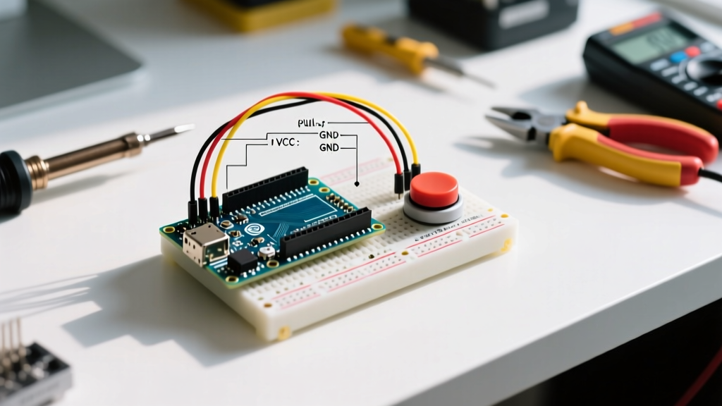
Step 1: Wiring the Arduino Push Button (Internal Pull-Up Method)
For 95% of hobbyist and prototyping applications, the internal pull-up method is superior due to its minimal component count. Here is the exact wiring procedure:
- Insert your tactile switch into the breadboard so the pins straddle the center trench.
- Connect one side of the switch (e.g., Pin 1a) directly to the Arduino GND pin.
- Connect the opposite side of the switch (e.g., Pin 2a) to Arduino Digital Pin 2.
- Leave the other two switch pins (1b and 2b) disconnected to avoid short circuits.
By configuring Pin 2 as INPUT_PULLUP in your sketch, the microcontroller internally connects a ~20kΩ to ~50kΩ resistor to the 5V rail. When the switch is open, Pin 2 reads HIGH. When pressed, the switch bridges Pin 2 to GND, pulling the voltage to 0V (LOW).
Writing the Firmware: Non-Blocking Software Debounce
The most common mistake beginners make when coding an Arduino push button is relying on the delay() function to wait out the bounce period. Using delay(50) halts the entire microcontroller, preventing you from reading sensors, updating displays, or managing motor control loops simultaneously. Instead, we use a state-tracking approach with the millis() timer.
Step 2: Implementing the Debounce Algorithm
According to embedded systems expert Jack Ganssle's definitive guide on debouncing, mechanical switches typically exhibit bounce times ranging from 1ms to 5ms. Setting a software debounce window of 50ms provides a massive safety margin without introducing noticeable input lag to the user.
const int buttonPin = 2;
const int ledPin = 13;

int ledState = HIGH;
int buttonState = HIGH;
int lastReading = HIGH;
unsigned long lastDebounceTime = 0;
const unsigned long debounceDelay = 50; // 50ms safety margin

void setup() {
  pinMode(buttonPin, INPUT_PULLUP);
  pinMode(ledPin, OUTPUT);
  digitalWrite(ledPin, ledState);
}

void loop() {
  int currentReading = digitalRead(buttonPin);

  // Check if the reading has changed (either from noise or a real press)
  if (currentReading != lastReading) {
    lastDebounceTime = millis(); // Reset the timer
  }

  // If the state has been stable for longer than the debounce delay
  if ((millis() - lastDebounceTime) > debounceDelay) {
    if (currentReading != buttonState) {
      buttonState = currentReading;

      // Trigger action only on the HIGH-to-LOW transition (Press event)
      if (buttonState == LOW) {
        ledState = !ledState;
        digitalWrite(ledPin, ledState);
      }
    }
  }
  lastReading = currentReading;
}
Hardware Debouncing Alternatives for Mission-Critical Designs
While software debouncing is perfect for general maker projects, industrial environments with high electromagnetic noise or strict real-time constraints may require hardware-level filtering. If your Arduino push button is located meters away from the MCU via a long cable, the wire acts as an antenna, and software debouncing might fail to filter out induced voltage spikes.
The RC Low-Pass Filter Method
By placing a resistor and a capacitor in an RC network, you can physically smooth out the voltage spikes caused by contact bounce. A standard configuration uses a 10kΩ series resistor and a 0.1µF ceramic capacitor to ground. This creates a time constant ($\tau = R \times C$) of 1 millisecond. The capacitor absorbs the rapid micro-spikes of the bouncing contacts, while the resistor limits the current discharge when the switch closes. For sharper logic transitions, the output of this RC filter can be fed through a Schmitt trigger IC, such as the 74HC14 hex inverter, which All About Circuits highly recommends for cleaning up slow-rising digital signals.
Troubleshooting Common Push Button Failures
Even with perfect code and wiring, physical components degrade. Here are the most frequent failure modes encountered in the field and how to diagnose them:
- Contact Oxidation: Standard tactile switches use silver-alloy contacts. In high-humidity environments, silver oxide builds up, increasing contact resistance from a nominal <100mΩ to over 10Ω. This causes voltage drops that the Arduino might fail to register as a solid LOW. Solution: Specify switches with gold-flashed contacts for low-voltage, low-current logic circuits.
- ESD Damage to GPIO: Touching a metal-capped push button can transfer thousands of volts of electrostatic discharge directly into the microcontroller pin, permanently destroying the input buffer. Solution: Add a 100nF capacitor in parallel with the switch and a 1kΩ series resistor between the switch and the GPIO pin to limit transient current.
- Mechanical Fatigue: The Omron B3F series is rated for 100,000 to 3,000,000 cycles depending on the specific model. If your button feels 'mushy' or fails to return to the UP state, the internal beryllium copper dome has fatigued and the component must be replaced.
Frequently Asked Questions
Can I use the internal pull-up resistor for matrix keypads?
Yes, but be cautious of 'ghosting'. When building a 4x4 matrix with Arduino push buttons, you must enable internal pull-ups on the column pins and drive the row pins LOW sequentially. If multiple buttons are pressed simultaneously without isolation diodes, current can backfeed through the grid, causing false readings.
Why does my button trigger randomly when a motor turns on nearby?
This is caused by EMI and ground bounce. High-current inductive loads like DC motors inject noise back into the shared ground plane. Always use optoisolators or separate ground planes with a single star-ground connection point when mixing sensitive logic inputs like push buttons with high-power motor drivers.