
The Illusion of Cross-Platform Code
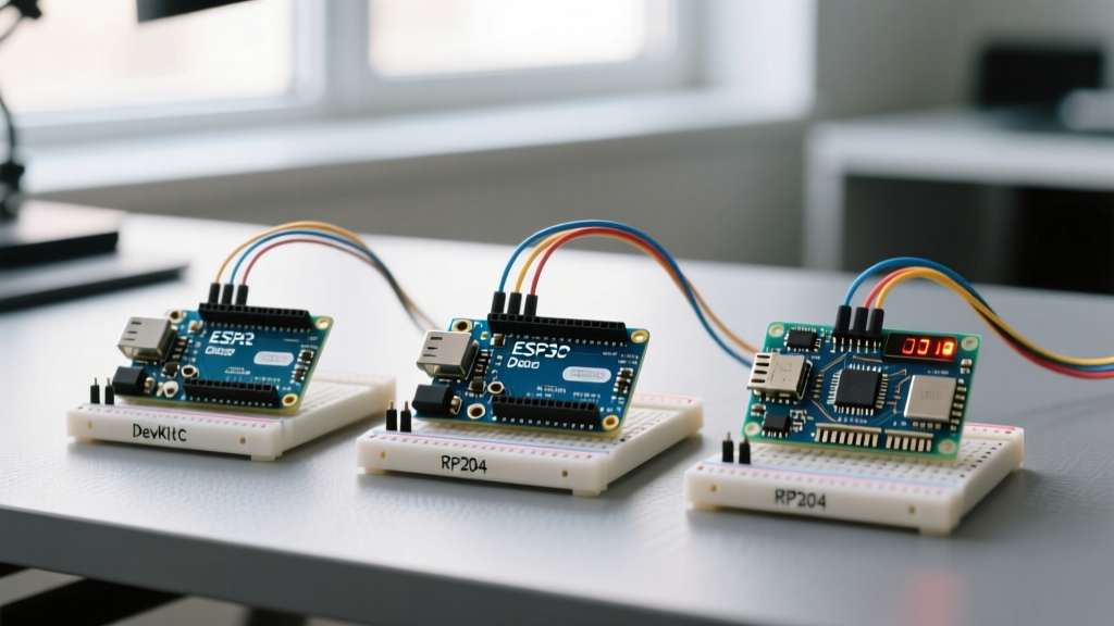
The Arduino IDE has long promised a unified coding experience across wildly different silicon architectures. At the heart of this abstraction is the pinMode() function. While it successfully abstracts away direct register manipulation for beginners, relying on pinMode() to behave identically across an ATmega328P, an ESP32-S3, and a Raspberry Pi RP2040 is a recipe for intermittent hardware failures. As we navigate the maker landscape in 2026, where multi-architecture project boxes are the norm, understanding the electrical and logical realities behind this single function is critical for robust firmware design.
This compatibility guide dissects how pinMode() operates at the silicon level across the three dominant microcontroller families in the Arduino ecosystem: AVR, Xtensa/RISC-V (ESP32), and ARM Cortex-M (RP2040/RP2350). We will cover internal pull-up/pull-down resistances, logic level thresholds, and catastrophic edge cases like boot-looping strapping pins.
The Baseline: AVR Architecture (ATmega328P)
When most developers think of pinMode(), they are thinking of the 8-bit AVR architecture, specifically the ATmega328P found on the Uno R3 and Nano. According to the official Arduino pinMode Reference, the function accepts INPUT, OUTPUT, and INPUT_PULLUP.
Electrical Characteristics and Register Mapping
On an AVR, calling pinMode(pin, OUTPUT) sets the corresponding bit in the Data Direction Register (DDRx) to 1. Calling INPUT clears it to 0. The magic happens with INPUT_PULLUP: it clears the DDRx bit and simultaneously sets the corresponding bit in the PORTx register, activating the internal silicon resistor.
- Pull-up Resistance: Nominally 20kΩ to 50kΩ. This wide tolerance is temperature and voltage-dependent.
- Pull-down Support: Native AVRs do not have internal pull-down resistors. Attempting to use a theoretical
INPUT_PULLDOWNwill result in a compilation error on standard AVR cores. - Logic Levels: 5V tolerant. A logical HIGH threshold (VIH) is typically 0.6 * VCC (3.0V on a 5V system).
- Current Limits: Absolute maximum is 40mA per pin, but 20mA is the recommended continuous limit to prevent silicon degradation.
The Xtensa and RISC-V Shift: ESP32 Families
The ESP32 ecosystem, including the classic ESP32-WROOM-32E and the newer ESP32-S3 and ESP32-C3 (RISC-V) variants dominating 2026 IoT projects, utilizes a highly complex GPIO matrix. The pinMode() function here interacts with the IO MUX and the GPIO matrix router rather than simple port registers.
RTC GPIOs vs. Digital GPIOs
Unlike the AVR, the ESP32 splits its pins into standard digital GPIOs and Real-Time Clock (RTC) GPIOs. RTC GPIOs can remain active during deep sleep. Crucially, internal pull-down resistors are only available on RTC GPIOs (e.g., GPIO 0, 2, 4, 12-15, 25-27, 32-39 on the original ESP32). If you attempt pinMode(16, INPUT_PULLDOWN) on a classic ESP32, the core will silently fail or throw a runtime warning, leaving the pin floating and susceptible to EMI noise.
For comprehensive GPIO routing details, hardware designers should consult the Espressif GPIO API Reference.
- Pull-up Resistance: Approximately 45kΩ.
- Pull-down Resistance: Approximately 45kΩ (RTC pins only on classic ESP32; widely available on ESP32-S3/C3).
- Logic Levels: Strictly 3.3V. Applying 5V to an ESP32 pin configured as
INPUTwill permanently damage the silicon latch.
The Cortex-M Evolution: RP2040 and RP2350
The Raspberry Pi Pico (RP2040) and the newer Pico 2 (RP2350) utilize ARM Cortex-M0+ and Cortex-M33/RISC-V cores, respectively. Their GPIO banks are highly uniform, lacking the fragmented RTC/Digital split of the ESP32, but they introduce their own pinMode() quirks.
Pads and Pull States
On the RP2040, pinMode() configures the SIO (Single-Cycle IO) block and the pad control registers. The internal pull resistors are notably weaker than those on AVR or ESP32.
- Pull-up / Pull-down Resistance: Typically 50kΩ to 80kΩ. This higher resistance means RP2040 pins are more susceptible to capacitive coupling and high-frequency noise if left unshielded in industrial environments.
- Drive Strength: The RP2040 allows software configuration of drive strength (2mA, 4mA, 8mA, 12mA), though the standard Arduino
pinMode()wrapper defaults to 4mA. To change this, you must drop into the Pico C/C++ SDK usinggpio_set_drive_strength(). - Logic Levels: 3.3V. The RP2350 introduces a 5V-tolerant VBUS sense, but standard GPIOs remain 3.3V.
For deeper silicon-level pad configurations, refer to the Raspberry Pi RP2040 Hardware Documentation.
Cross-Architecture Compatibility Matrix
When porting legacy code to modern boards, use this matrix to predict how your pinMode() configurations will translate electrically.
| Feature | AVR (ATmega328P) | ESP32 (Classic/S3) | RP2040 / RP2350 |
|---|---|---|---|
| Native Logic Level | 5.0V | 3.3V | 3.3V |
| INPUT_PULLUP Value | 20kΩ - 50kΩ | ~45kΩ | 50kΩ - 80kΩ |
| INPUT_PULLDOWN Support | No | Yes (Varies by pin/family) | Yes (All standard GPIOs) |
| Max Continuous Sink/Source | 20mA | 40mA (Total package limits apply) | ~12mA (Configurable) |
| Default State on Boot | High-Z (INPUT) | High-Z (Some strapping pins pulled) | High-Z (INPUT) |
Critical Edge Cases and Boot Failures
The most dangerous aspect of pinMode() compatibility is not the resistance value; it is the boot sequence. Microcontrollers use specific pins to determine boot modes (e.g., flash vs. ROM bootloader). If your setup() function reconfigures these pins incorrectly, or if external circuitry fights the internal pull-ups during the first 500 milliseconds of power-on, the board will brick itself into a boot loop.
WARNING: ESP32 Strapping Pins
On the classic ESP32, GPIO 0, 2, 12, and 15 are strapping pins. If you usepinMode(12, INPUT_PULLUP)and GPIO 12 is pulled high during boot, the ESP32 will attempt to boot from an external SDIO slave or switch the flash voltage to 1.8V, resulting in an immediate boot failure. Never use strapping pins for standard user inputs without external hardware overrides.
The I2C / TWI Pin Conflict
On AVR boards, A4 and A5 (or dedicated SDA/SCL pins) are hardwired to the TWI (Two-Wire Interface) peripheral. Calling pinMode(A4, OUTPUT) and then toggling it will physically fight the I2C hardware state machine, potentially corrupting the I2C bus or damaging the port driver if an external pull-up is tied to 5V. On the ESP32 and RP2040, I2C is mapped via a flexible matrix, meaning any pin can be SDA/SCL. However, if you initialize Wire.begin() and subsequently call pinMode() on those same pins, you will overwrite the open-drain configuration set by the Wire library, breaking I2C communication.
Writing Portable pinMode Macros
To maintain a single codebase that compiles safely across a Nano, an ESP32-S3, and a Pico 2 in 2026, rely on preprocessor directives to handle architectural limitations gracefully. Below is a robust framework for handling pull-downs, which are unsupported on AVR:
#if defined(ARDUINO_ARCH_AVR)
  // AVR Fallback: No internal pull-downs exist.
  // We must use INPUT and rely on an external 10k resistor.
  #define SAFE_INPUT_PULLDOWN(pin) pinMode(pin, INPUT)
  #warning 'AVR does not support internal pull-downs. Ensure external resistors are populated.'
#elif defined(ARDUINO_ARCH_ESP32)
  // ESP32: Verify pin is RTC capable if using classic ESP32
  #define SAFE_INPUT_PULLDOWN(pin) pinMode(pin, INPUT_PULLDOWN)
#elif defined(ARDUINO_ARCH_RP2040) || defined(ARDUINO_ARCH_RP2350)
  // Pico: Fully supported across the GPIO bank
  #define SAFE_INPUT_PULLDOWN(pin) pinMode(pin, INPUT_PULLDOWN)
#else
  #define SAFE_INPUT_PULLDOWN(pin) pinMode(pin, INPUT)
#endif

void setup() {
  // Safely configure a button pin across all architectures
  SAFE_INPUT_PULLDOWN(4);
}
Summary for Hardware Designers
The pinMode() function is a convenience, not a guarantee. When designing PCBs or wiring harnesses that must remain compatible with multiple Arduino-compatible dev boards, never rely solely on INPUT_PULLUP for critical reset lines or safety interlocks. The 20kΩ variance on AVR versus the 80kΩ weakness on the RP2040 can mean the difference between a clean logic transition and a floating pin susceptible to motor-induced EMI. Always populate external 4.7kΩ to 10kΩ resistors on mission-critical inputs, and rigorously map out the boot-strapping requirements of your target silicon before writing your first line of setup() code.