
The Limits of Basic Touch Sensitive Switch Arduino Prototypes
When you first build a touch sensitive switch Arduino prototype, you likely reach for a TTP223 module or a bare copper wire tied to a digital pin with a 10M-ohm pull-up resistor. For a breadboard proof-of-concept, these methods work flawlessly. However, as you transition from a messy wiring setup to a finished product enclosed in 3D-printed PLA or laser-cut acrylic, the limitations of basic capacitive sensing quickly surface.
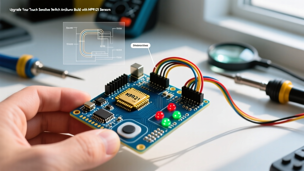
Basic modules suffer from fixed, uncalibrated sensitivity thresholds. They are notoriously susceptible to electromagnetic interference (EMI) from nearby unshielded relays, switching power supplies, and even the humidity in the room. A slight change in ambient temperature can cause a TTP223 module to latch into a 'ghost touch' state, rendering your device unusable. To build a reliable, commercial-grade interface, you must migrate to a dedicated I2C capacitive touch controller. This guide details the hardware and software migration path from legacy single-pin touch setups to the industry-standard NXP MPR121 controller.
Migration Matrix: Choosing Your Upgrade Path
Before ripping up your existing wiring, evaluate which upgrade path fits your project's constraints. As of 2026, while native MCU touch pins have improved, dedicated I2C controllers still offer superior noise rejection for retrofitted ATmega328P and SAMD21 projects.
| Sensor Type | Cost (Approx.) | Channels | Interface | Noise Rejection & Tuning | Best Use Case |
|---|---|---|---|---|---|
| TTP223 (Baseline) | $0.50 | 1 | Digital GPIO | Poor (Fixed threshold) | Simple single-button toys |
| NXP MPR121 | $6.95 (Breakout) | 12 | I2C | Excellent (Deep register tuning) | Multi-key panels, glass enclosures |
| Microchip CAP1188 | $7.95 (Breakout) | 8 | I2C/SPI | Good (Built-in LED drivers) | Illuminated touch buttons |
| ESP32-S3 Native | $0.00 (Integrated) | 14 | Internal Peripheral | Moderate (Requires software filtering) | New IoT designs using ESP32-S3 |
For the vast majority of touch sensitive switch Arduino upgrades, the MPR121 offers the best balance of deep configurability, extensive community library support, and the ability to sense through thick dielectrics.
Hardware Migration: Designing the Electrodes
The most critical failure point in capacitive touch migration is treating the electrode as an afterthought. Unlike the TTP223, which includes a built-in spring and a fixed PCB pad, the MPR121 relies entirely on your custom electrode geometry.
Dielectric Thickness and Electrode Sizing
According to the NXP AN3894 Capacitive Sensor Design Guide, the electrode size must scale linearly with the thickness of your enclosure's dielectric (the plastic or glass cover). If you are using 3mm cast acrylic, a solid copper electrode size of 10x10mm to 15x15mm is optimal. If you scale up to 5mm tempered glass, you must increase the electrode area to at least 20x20mm to maintain a sufficient signal-to-noise ratio (SNR).
PCB Layout Rules for the MPR121
If you are migrating from copper tape to a custom PCB, strict layout rules apply:
- Hatched Ground Pour: Never place a solid ground plane directly beneath the touch electrodes. This creates a massive parasitic capacitance that desensitizes the MPR121. Instead, use a cross-hatched ground pour (typically 45-degree angles with 8mil traces and 16mil spacing) to shield against EMI without ruining the baseline capacitance.
- Trace Routing: Keep the traces connecting the MPR121 IC to the electrodes as short and uniform in length as possible. A difference in trace length of just 15mm can result in a baseline capacitance variance of 2-3 pF, making uniform threshold tuning impossible.
- Keep-Out Zones: Route high-current traces (like those driving 5V relays or Neopixel data lines) at least 2mm away from any touch electrode trace.
Pro-Tip for 3D Printed Enclosures: If your enclosure is printed in PLA or PETG, the infill pattern creates microscopic air gaps that change the effective dielectric constant. Print the touch surface area at 100% infill with a minimum 2mm top solid layer to ensure a consistent capacitive baseline across all buttons.
Software Migration: Rewiring the Codebase
Moving from a simple digitalRead() to an I2C-based architecture requires restructuring your Arduino sketch. The MPR121 communicates via the Arduino Wire (I2C) library, defaulting to address 0x5A. You will need to install the Adafruit_MPR121 library via the Library Manager.
Initialization and Basic Reading
Replace your legacy pin-mode setup with the I2C initialization block. The MPR121 features an auto-calibration routine that runs on startup, measuring the baseline capacitance of your electrodes before the user touches the device.
#include <Wire.h>
#include <Adafruit_MPR121.h>

Adafruit_MPR121 cap = Adafruit_MPR121();
uint16_t lastTouched = 0;

void setup() {
  Serial.begin(115200);
  if (!cap.begin(0x5A)) {
    Serial.println("MPR121 not found, check wiring?");
    while (1);
  }
  Serial.println("MPR121 Initialized.");
}

void loop() {
  uint16_t curTouched = cap.touched();
  if (curTouched != lastTouched) {
    for (uint8_t i = 0; i < 12; i++) {
      if ((curTouched >> i) & 1) {
        Serial.print("Touched: Electrode "); Serial.println(i);
      }
    }
    lastTouched = curTouched;
  }
  delay(50);
}
Deep Register Tuning for False-Trigger Immunity
The default library settings are highly sensitive, designed for bare copper. When migrating to an enclosed touch sensitive switch Arduino project, you must manually write to the MPR121's configuration registers to prevent false triggers. You can do this by adding direct I2C writes in your setup() function immediately after cap.begin().
- Touch/Release Thresholds (Registers 0x26 - 0x41): The default touch threshold is usually
0x0F(15). For a 3mm acrylic enclosure, increase this to0x20(32) to require a more deliberate finger press. Set the release threshold to exactly 50% of the touch threshold (e.g.,0x10) to provide hysteresis and prevent 'chatter' when the finger is lifted. - Debounce Configuration (Register 0x5B): By default, the chip registers a touch on the very first sample that crosses the threshold. In noisy environments, write
0x22to this register. This forces the MPR121 to require two consecutive samples above the threshold for a touch, and two below for a release, effectively filtering out microsecond EMI spikes. - AFE Configuration 1 (Register 0x21): This controls the Charge Limit and SFI (SFI). If your project uses a switching power supply (SMPS) that introduces 50/60Hz noise, set the SFI bits to
0x10to enable the maximum filtering algorithm, averaging more samples per reading at the cost of a slightly higher latency (approx. 16ms).
Real-World Edge Cases and Troubleshooting
Even with perfect code and layout, real-world deployments introduce edge cases that basic modules simply ignore.
The Water Droplet Problem
Capacitive sensors cannot distinguish between a human finger and a droplet of water, as both have a high dielectric constant. If your Arduino project is deployed in a kitchen or bathroom, a single condensation droplet on the enclosure will register as a continuous touch. To mitigate this, implement a 'water rejection' algorithm in your firmware: if an electrode registers a continuous touch for longer than 5 seconds, the software should flag it as an environmental fault, recalibrate the baseline by briefly resetting the MPR121 via the RST pin, and ignore the input until the capacitance drops back to normal.
Grounding and the Human Body Model
Capacitive touch relies on the human body acting as a ground sink to draw charge away from the electrode. If your Arduino is powered by an ungrounded 5V USB wall adapter (common in cheap 2-prong chargers), the entire system floats. This floating ground can cause the MPR121's baseline to drift wildly, leading to missed touches. If you must use an ungrounded supply, ensure your PCB includes a large, dedicated 'grounding bezel' electrode connected to the system ground, and instruct users to rest their palm on the device while pressing the buttons.
Summary
Migrating a touch sensitive switch Arduino project from a basic TTP223 to a dedicated MPR121 controller transforms a fragile prototype into a robust, commercial-ready interface. By respecting dielectric thickness, implementing hatched ground pours, and manually tuning the I2C debounce and threshold registers, you eliminate the ghost touches and EMI vulnerabilities that plague basic setups. While the initial hardware cost increases by a few dollars, the dramatic reduction in firmware workarounds and the vastly improved user experience make the MPR121 the undisputed upgrade path for serious makers and engineers.