
The Core Challenge: Logic Levels and BEC Voltages
Interfacing high-power motor drivers with low-voltage microcontrollers is a foundational skill in robotics and UAV design. When evaluating an electronic speed controller Arduino setup, the most common points of catastrophic failure do not stem from code, but from hardware incompatibilities—specifically, Battery Eliminator Circuit (BEC) voltage mismatches and logic-level thresholds.
Most standard hobby ESCs utilize a 3-wire interface: Power (Red), Ground (Black/Brown), and Signal (White/Yellow/Orange). While the signal wire expects a standard Pulse Width Modulation (PWM) square wave, the power wire often outputs a regulated voltage intended to power an RC receiver. Connecting this BEC output directly to an Arduino requires strict adherence to the microcontroller's absolute maximum voltage ratings.
Critical Warning: The ATmega328P (used in the Uno and Nano) has an absolute maximum operating voltage of 5.5V. Many modern Switching BECs (SBECs) output 6.0V to 7.4V to support high-voltage servos. Feeding 6.0V directly into the Arduino's
5Vpin bypasses the onboard linear regulator and will instantly destroy the microcontroller.
Logic Level Thresholds: 5V vs. 3.3V MCUs
Standard hobby ESCs (running Simonk or BLHeli_S firmware) typically register a logic HIGH at anything above 2.5V. This makes them natively compatible with both 5V AVR-based Arduinos and 3.3V ARM/ESP32 boards. However, older or industrial-grade opto-isolated ESCs often require a minimum of 4.5V to reliably detect a logic HIGH. If you are using a 3.3V MCU like the Arduino Due or an ESP32 with an opto-isolated ESC, you must implement a logic level shifter (such as a 74AHCT125 buffer or a BSS138 MOSFET circuit) to step the 3.3V PWM signal up to 5V.
Electronic Speed Controller Arduino Compatibility Matrix
The protocol your ESC uses dictates the required Arduino library and hardware timer configuration. Below is a compatibility matrix for standard protocols used in 2026.
| ESC Protocol | Signal Frequency | Pulse Width Range | Recommended Arduino Library | MCU Compatibility |
|---|---|---|---|---|
| Standard PWM | 50 Hz (20ms period) | 1000µs - 2000µs | Servo.h (Built-in) |
All (AVR, ARM, ESP32) |
| OneShot125 | 125 Hz - 500 Hz | 125µs - 250µs | Hardware Timer PWM / PWMDriver |
ARM (Due/Teensy), ESP32 |
| DShot600 | 375 kHz (Digital) | Digital Bitstream (16-bit) | DShot (via DMA) |
ARM, ESP32 (Requires DMA) |
| Serial/I2C Telemetry | N/A (Data overlay) | 9600-115200 Baud | SoftwareSerial / Wire |
All (with specific ESC firmware) |
For 90% of general robotics applications (rover drives, conveyor belts, basic thrusters), Standard PWM via the built-in Arduino Servo Library is the most reliable choice. The library abstracts the hardware timers to generate the precise 50Hz signal required by the ESC's internal microcontroller.
Wiring Configurations: Opto-Isolated vs. BEC-Equipped
The physical wiring topology changes drastically depending on whether your ESC features an internal BEC or is opto-isolated.
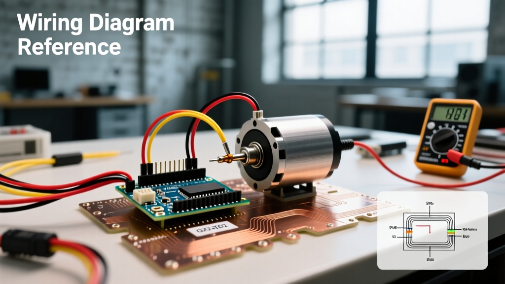
Configuration A: BEC-Equipped ESC (Standard Hobby Grade)
These ESCs step down the main battery voltage (e.g., 11.1V LiPo) to 5.0V.
- ESC Red Wire (BEC 5V): Connect to Arduino
5Vpin (ONLY if verified at exactly 5.0V with a multimeter) orVinpin (if 6.0V+). - ESC Black Wire (GND): Connect to Arduino
GND. Never omit the common ground; the PWM signal requires a shared reference plane. - ESC White Wire (Signal): Connect to any Arduino digital PWM-capable pin (e.g., Pin 9).
Edge Case: If you are powering the Arduino via USB simultaneously, a backfeed conflict can occur between the USB 5V rail and the ESC BEC 5V rail. To prevent damage to your computer's USB port or the Arduino's polyfuse, cut the 5V trace on the Arduino's USB connector or use a USB isolator.
Configuration B: Opto-Isolated ESC (Industrial / High-Voltage)
Opto-isolated ESCs use an internal optocoupler to electrically separate the high-voltage motor side from the low-voltage signal side. They do not output power on the red wire.
- External 5V Source: Required to power the Arduino and the ESC's internal optocoupler LED.
- ESC Red Wire: Connect to External 5V Source.
- ESC Black Wire: Connect to External Source GND and Arduino GND.
- ESC White Wire: Connect to Arduino Signal Pin.
Signal Integrity and Brownout Mitigation
Brushless motors draw massive transient currents during startup or rapid direction reversals. A 20A rated ESC can easily pull 50A+ for a few milliseconds. This causes severe voltage sag on the battery, which translates to ripple on the BEC output. If the BEC voltage drops below the Arduino's brownout detection threshold (typically 2.7V for the ATmega328P), the microcontroller will reset, sending erratic PWM signals that can cause the ESC to latch up or the motor to spin out of control.
The Decoupling Capacitor Solution
To stabilize the logic voltage, you must add bulk capacitance near the microcontroller. Solder a 470µF 16V Low-ESR Electrolytic Capacitor directly across the 5V and GND pins on the Arduino header. For high-noise environments, parallel this with a 100nF (0.1µF) ceramic capacitor to filter high-frequency switching noise generated by the ESC's MOSFETs. Understanding PWM fundamentals and signal noise is critical when routing these wires; always use twisted-pair wiring for the Signal and Ground lines to minimize electromagnetic interference (EMI) from the motor phases.
The Arming Sequence: Why Your Motor Won't Spin
A frequent troubleshooting scenario for beginners is an ESC that refuses to spin the motor, often accompanied by a repeating 'beep-beep' error tone. This is not a hardware failure; it is a security arming sequence.
To prevent accidental startup, ESC firmware requires a specific low-throttle validation period upon boot. Using the Servo.h library, you must send a 1000µs (1ms) pulse for a minimum of 1 to 3 seconds before sending any throttle commands.
Correct Arming Logic Flow:
- Initialize Servo library and attach to pin.
- Write
1000(microseconds) immediately in thesetup()function. - Delay for
2000milliseconds. - Listen for the ESC confirmation tone (usually a rising musical scale).
- Begin writing throttle values (1000 to 2000) in the
loop().
If the signal wire is disconnected or the PWM frequency drifts during this 2-second window, the ESC will enter a failsafe timeout and refuse to arm until power is cycled.
2026 Market Models and Pricing for Makers
Selecting the right ESC depends on your project's telemetry and current requirements. Here are three benchmark models frequently used in Arduino-based robotics:
- Hobbywing Skywalker 20A ($14 - $18): The gold standard for basic Arduino rovers and educational kits. Features a reliable 5V/2A linear BEC. Firmware is locked to standard 50Hz PWM, making it perfectly compatible with
Servo.hout of the box. - Makerfocus 40A BLHeli_32 ($28 - $35): Designed for drones but excellent for advanced robotics requiring bidirectional control and telemetry. Supports DShot protocols and features a current sense resistor that can be read by the Arduino's ADC via an op-amp circuit for closed-loop torque control.
- Castle Creations Talon 35 ($48 - $55): An industrial-grade opto-isolated ESC. Ideal for high-voltage (up to 6S LiPo / 22.2V) applications where electrical isolation between the motor phases and the Arduino logic ground is mandatory to prevent ground-loop interference.
Summary Checklist for Deployment
Before applying main battery power to your electronic speed controller Arduino circuit, verify the following:
- Verify BEC output voltage with a multimeter before connecting to the MCU.
- Ensure a common ground exists between the ESC, the MCU, and any external logic shifters.
- Confirm the arming sequence (1000µs for 2 seconds) is present in your initialization code.
- Install bulk decoupling capacitors on the logic power rail to prevent brownout resets.
For deeper insights into hardware timer configurations and advanced PWM signal generation, consult the official microcontroller documentation specific to your board's architecture.