
The Evolution of the Stop Light Arduino Prototype
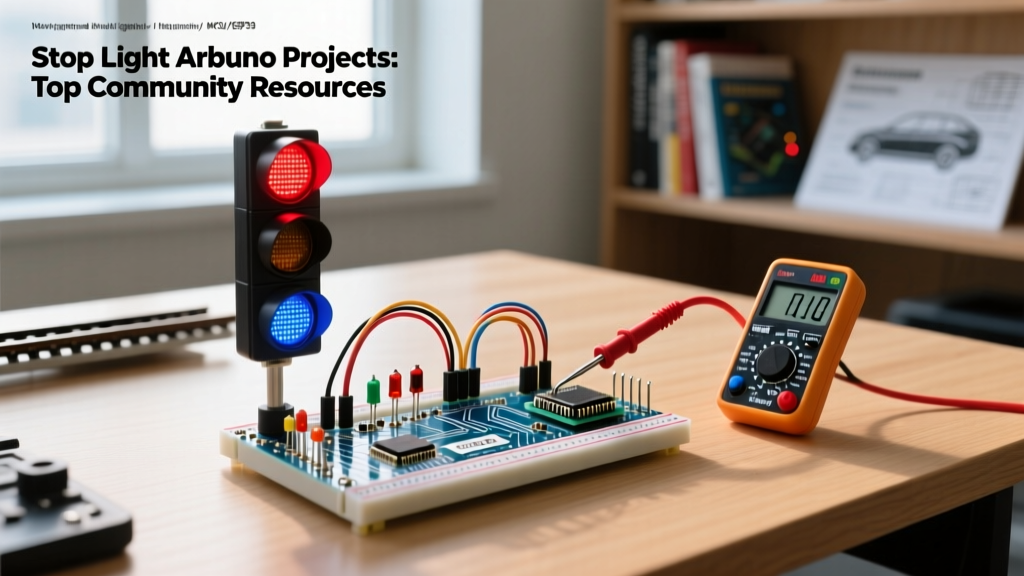
When makers and engineers search for a reliable stop light arduino setup, the projects generally span three distinct domains: educational tabletop models, high-fidelity model railway signaling, and high-power automotive auxiliary brake lights. In 2026, the maker community has moved far beyond simple delay loops and basic 5mm diffused LEDs. Today is builds require robust finite state machines, addressable RGB optics, and automotive-grade transient protection. This community resource roundup synthesizes the best hardware topologies, wiring practices, and code architectures currently dominating the open-source repositories and maker forums.
The Hardware Matrix: Choosing the Right Microcontroller
Selecting the correct board is the first critical step. While the classic Uno remains popular, the community has largely migrated to more specialized silicon depending on the scale of the traffic light project. Below is a comparison of the most recommended microcontrollers for intersection and signaling logic.
| Microcontroller | Est. Price (2026) | Logic Level | Best Use Case |
|---|---|---|---|
| Arduino Nano Every | $12.50 | 5V | Standard 5mm LED tabletop intersections |
| Arduino Uno R4 Minima | $20.00 | 5V | Complex state-machine pedestrian crossings |
| ESP32-S3-DevKitC | $8.50 | 3.3V | Connected V2X smart intersections via WiFi |
| ATtiny85 | $2.10 | 5V | Compact automotive 3rd brake light pulse modules |
Classic 5mm Arrays vs. Addressable RGB Optics
The visual output of your stop light arduino project dictates your wiring topology. The community is currently split between traditional discrete LEDs and modern addressable strips.
Discrete 5mm Diffused LEDs
For realistic scale models, discrete LEDs are preferred. However, proper current limiting is mandatory. Makers frequently miscalculate resistor values by assuming a uniform forward voltage (Vf). In reality, a standard red LED has a Vf of roughly 2.0V, while green and yellow sit around 2.2V and 2.1V respectively. Assuming a 5V Vcc and a target current of 20mA, Ohm is Law dictates a 150-ohm resistor for red, and a 140-ohm resistor for green. The community standard is to use 150-ohm or 180-ohm E12 series resistors across the board to simplify inventory, accepting a slight variance in luminosity.
Addressable WS2812B (NeoPixel) Assemblies
For full-scale intersections or UK-style Pelican crossings, makers use WS2812B LED rings or strips. This allows for smooth amber fading and custom pedestrian countdown timers. However, power injection is a major point of failure. According to the Adafruit NeoPixel Power Guide, each pixel can draw up to 60mA at full white brightness. A standard 4-way intersection using 120 total pixels requires a dedicated 5V 8A power supply. Never attempt to power an addressable stop light array through the Arduino is onboard 5V pin, as this will instantly trip the polyfuse or destroy the voltage regulator.
Community Insight: 'Always use a 300 to 500 ohm resistor on the data line of your first WS2812B pixel, and place a 1000uF electrolytic capacitor across the 5V and GND power rails to absorb sudden current spikes when all lights turn red simultaneously.' — EEVblog Forum Contributor
High-Power Automotive Stop Lights: MOSFETs and Isolation
Integrating a stop light arduino system into a real vehicle, such as a custom sequential turn signal or a pulsing 3rd brake light, introduces severe electrical hazards. A vehicle is alternator runs at 13.8V to 14.4V, and load dump transients can spike well above 40V.
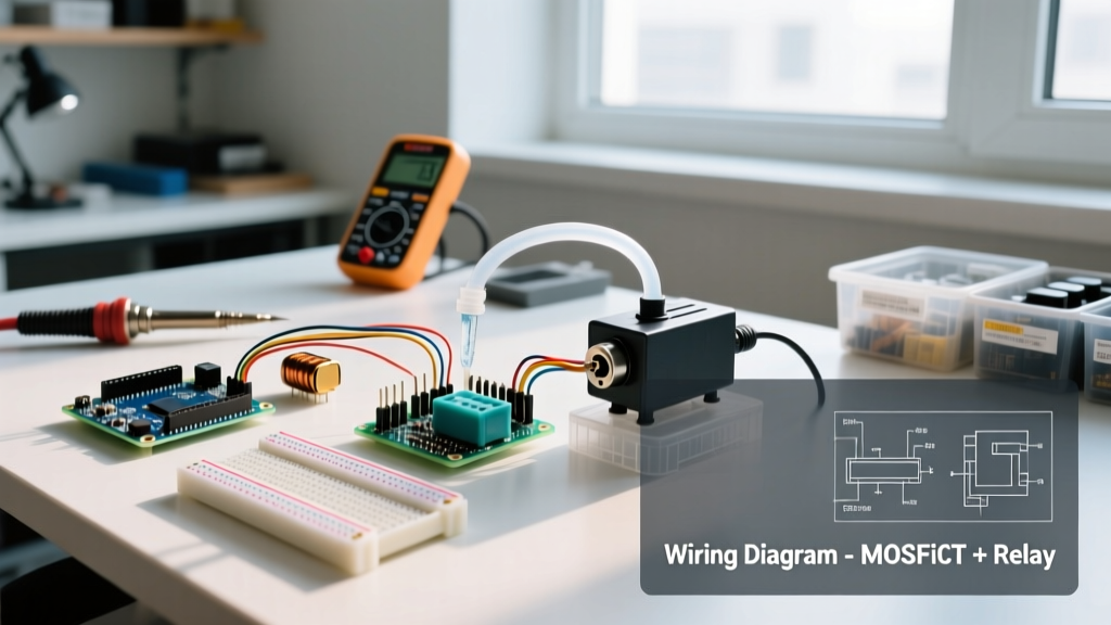
- Logic-Level MOSFETs: The community standard for switching 12V automotive bulbs is the IRLZ44N. Unlike standard MOSFETs, its gate threshold voltage (Vgs) is low enough to be fully enhanced by the Arduino is 5V logic output, eliminating the need for a secondary 12V gate driver.
- Galvanic Isolation: To protect the microcontroller from ground loops and voltage spikes, experienced makers use a PC817 optocoupler between the Arduino PWM pin and the MOSFET gate. This ensures that if the 12V side experiences a catastrophic short, the 5V logic side remains completely isolated.
- Snubber Networks: Incandescent automotive bulbs have a cold filament resistance that is roughly one-tenth of their hot resistance. This massive inrush current can cause localized voltage sags, triggering the Arduino is Brown-Out Detector (BOD) and causing random resets. Adding a 1000uF low-ESR capacitor on the microcontroller is power rail mitigates this edge case.
Non-Blocking Code Architecture
The most heavily criticized mistake in beginner stop light arduino code is the use of the delay() function. A traffic light is a real-time system; it must monitor pedestrian crosswalk buttons, emergency vehicle strobe detectors, and induction loop sensors simultaneously. If your code is stuck in a 30-second delay for the green light phase, it will be entirely blind to sensor inputs.
The community universally recommends utilizing the Arduino millis() reference to build a Finite State Machine (FSM). By tracking elapsed time without halting the processor, your intersection can instantly abort a green phase and trigger an emergency all-red sequence if an ambulance is detected.
Example FSM State Flow
- State GREEN: Main traffic flowing. Continuously poll pedestrian button via hardware interrupt.
- State AMBER: 3-second timeout. Clear intersection. Ignore new button presses.
- State RED: Main traffic stopped. Trigger pedestrian walk signal. Monitor cross-zone IR sensors.
- State RED_AMBER: 1.5-second prepare-to-go phase. Ensure cross-zone is clear before advancing.
Edge Case: PWM Rolling Shutter Flicker
If your stop light arduino project is intended for outdoor use where it might be recorded by dashcams, drones, or security cameras, standard 490Hz PWM will cause severe flickering and banding on video due to the rolling shutter effect. The community workaround is to reconfigure the Arduino is internal hardware timers to push the PWM frequency above 2kHz. On modern boards like the Uno R4 Minima, this is easily handled via the analogWriteFrequency() function, resulting in a visually smooth fade that cameras capture without artifacting.
Community Spotlight: Model Railway Block Signaling
One of the most active niches for stop light arduino builds is model railway automation. Makers use infrared (IR) reflectance sensors (like the TCRT5000) placed between the rails to detect the presence of a locomotive. When a train enters a 'block' section, the Arduino triggers a red signal aspect for the approaching block, preventing collisions. The Hackaday Traffic Light Archives feature numerous iterations of this concept, with advanced builders implementing I2C communication between multiple signal masts so the entire layout is aware of train positions in real-time.
Summary and Next Steps
Whether you are wiring a simple 5mm LED array for a school project or designing an optically isolated, MOSFET-driven sequential brake light for your daily driver, the stop light arduino ecosystem offers a solution. By adhering to community best practices—specifically regarding non-blocking FSM code, proper power injection for addressable LEDs, and automotive-grade transient protection—you can build signaling systems that are both visually impressive and electrically bulletproof.