
Decoding the 'Arduino Pie' Phenomenon
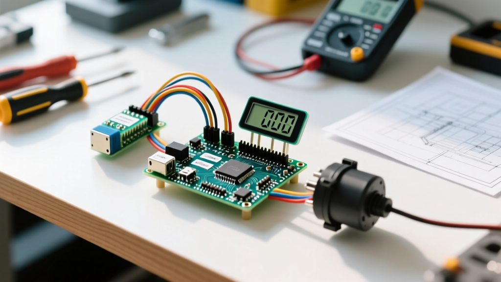
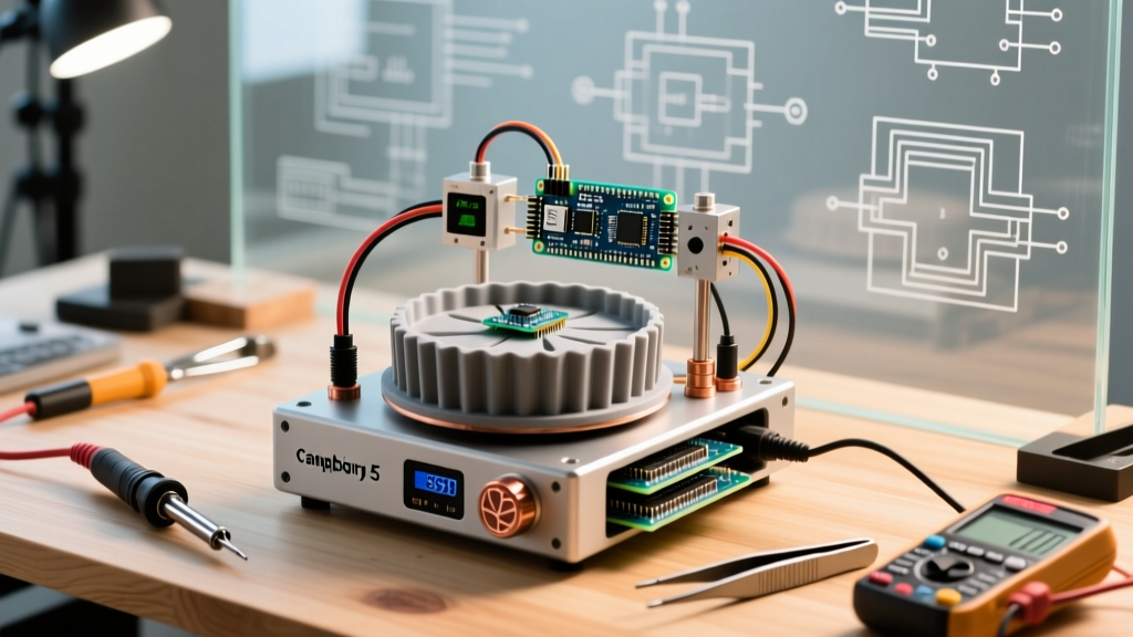
The maker community often encounters the search term 'arduino pie,' a fascinating linguistic quirk that points to two distinct but equally compelling corners of the DIY electronics world. On one hand, it represents the phonetic misspelling of 'Arduino Pi'—the highly sought-after integration of Arduino microcontrollers with Raspberry Pi single-board computers. On the other hand, it refers to a niche but beloved community tradition: building literal, PID-controlled automated pie-baking rigs. In this 2026 community resource roundup, we are bridging both worlds. Whether you are architecting a hybrid robotic vision system using a Raspberry Pi 5 and an Arduino Uno R4, or tuning a solid-state relay for the perfect pastry crust, this guide aggregates the most authoritative frameworks, hardware bill-of-materials (BOM), and GitHub repositories available today.
The 'Arduino Pi' Hybrid Architecture: Pi 5 Meets Uno R4
Integrating a high-level Linux environment with real-time hardware control is the cornerstone of advanced robotics and IoT. The Raspberry Pi 5 handles heavy computational lifting—such as running OpenCV computer vision models or ROS 2 Jazzy nodes—while the Arduino Uno R4 Minima manages deterministic, microsecond-level PWM motor control and sensor polling. However, the most common failure mode in community builds is logic-level mismatching. The Pi 5's BCM2712 SoC operates strictly at 3.3V logic, whereas the Uno R4's Renesas RA4M1 ARM Cortex-M4 runs at 5V. Directly wiring their I2C or UART pins will permanently destroy the Pi's GPIO bank.
Safe Hardware Bridging
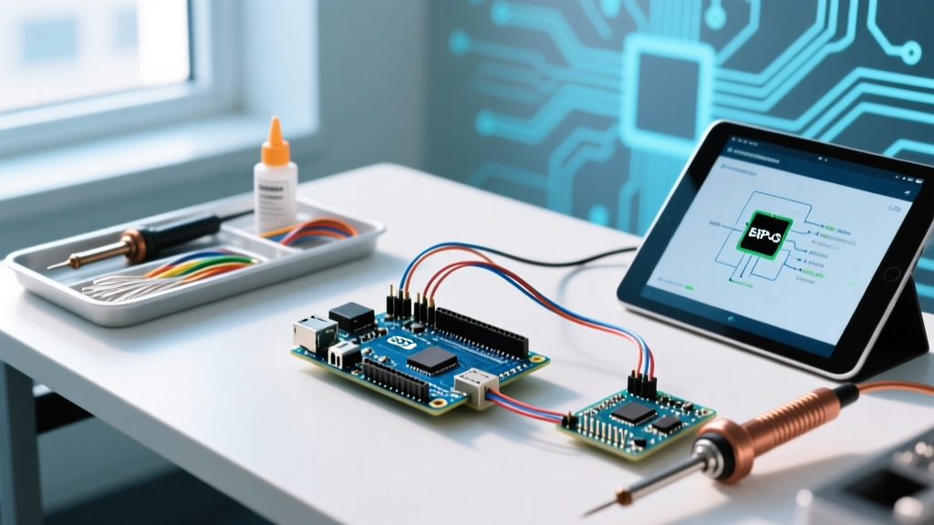
To safely bridge this gap, the community standard in 2026 is the Texas Instruments TXS0108E bidirectional logic level shifter, widely available on SparkFun (BOB-12009) or Adafruit (2705) breakouts for under $4. When wiring the I2C bus (Pi pins 3 and 5 to Arduino A4 and A5), you must route the Pi's 3.3V to the shifter's LV side and the Arduino's 5V to the HV side. Furthermore, I2C pull-up resistors on the Arduino side must be disabled (often by cutting a jumper pad on the module) to prevent the 5V line from back-feeding the Pi. For authoritative pinout and configuration details, always refer to the official Raspberry Pi configuration documentation.
Protocol Showdown: Bridging the Gap
Choosing the right communication protocol between the Pi and Arduino dictates your system's latency and throughput. Below is a breakdown of the most common methods used in hybrid rigs.
| Protocol | Max Baud / Speed | Avg Latency | Best Use Case | Wiring Complexity |
|---|---|---|---|---|
| USB-Serial (Firmata) | 115200 bps | ~4.5 ms | Basic sensor logging, simple LED control | Low (Direct USB cable) |
| UART (micro-ROS) | 921600 bps | < 1.0 ms | ROS 2 robotics, joint-state publishing | Medium (Requires logic shifter) |
| I2C Bus | 400 kHz (Fast) | ~0.5 ms | High-frequency sensor polling, interrupts | High (Requires pull-up management) |
| SPI Bus | 8 MHz | < 0.2 ms | High-speed data transfer, audio streaming | High (Strict master/slave wiring) |
For modern robotics applications, the community has overwhelmingly adopted micro-ROS. Unlike legacy Firmata setups that cap out at standard serial speeds, micro-ROS utilizes the micro-XRCE-DDS agent to publish and subscribe to ROS 2 topics directly from the Arduino's memory space. Over a 921600 baud UART connection, micro-ROS achieves sub-millisecond latency, making it the undisputed choice for autonomous rovers and robotic arms.
The Literal 'Arduino Pie': PID-Controlled Smart Baking
Moving from silicon to sustenance, the 'Arduino Pie' smart oven project is a masterclass in thermal dynamics and PID (Proportional-Integral-Derivative) control. Community members have successfully built automated pie-baking enclosures that maintain exact crust-browning temperatures by modulating a 500W 120VAC heating element, ensuring the filling sets without burning the lattice top.
Hardware BOM and Wiring Specifics
The hardware BOM for a safe, high-wattage thermal controller requires specific industrial components. Do not use standard mechanical relays; they will fail within a week due to contact arcing from rapid PWM switching. Instead, use a Crydom D2425 Solid State Relay (SSR), rated for 25A and 24-280VAC, which features built-in zero-crossing detection to minimize electromagnetic interference (EMI). For temperature feedback, bypass cheap thermistors and use a K-type thermocouple paired with a MAX6675 SPI breakout board. The MAX6675 provides cold-junction compensation and reads up to 1024°C with 0.25°C resolution, which is critical for the narrow 175°C to 190°C baking window required for fruit pies.
PID Tuning for Thermal Mass
Tuning the PID loop is where most makers hit a wall. Using the standard Arduino PID Library by Brett Beauregard (available via the Arduino Library Manager), set your sample time to 1000ms. Thermal systems are inherently slow; 10ms sampling introduces massive derivative noise. For a well-insulated 10-liter baking chamber, the community consensus baseline tuning via the Ziegler-Nichols method yields:
- Kp (Proportional): 15.2
- Ki (Integral): 0.8
- Kd (Derivative): 45.0
Set the controller to DIRECT mode and define your output limits between 0 and 255 for the SSR's PWM window. Use a 10-second time-proportioning window rather than high-frequency PWM to prolong the life of your heating element.
Top Community Repositories & Resources
To accelerate your build, leverage these battle-tested community repositories:
- pyFirmata2 (GitHub): The modern fork of the classic Python-to-Arduino bridge. Includes automatic port detection and asynchronous callback support for sensor streams. Ideal for quick Pi-to-Arduino prototyping without writing custom C++ firmware.
- micro_ros_arduino (GitHub): The official transport layer for running micro-ROS on Arduino boards. Includes pre-compiled static libraries for the Uno R4 and Nano RP2040 Connect, drastically reducing compilation times.
- OpenBake PID (Community Fork): A specialized fork of the Arduino PID library that includes anti-windup clamping and auto-tune routines specifically calibrated for high-thermal-mass cooking enclosures.
Edge Cases and Troubleshooting
Maker Warning: When running high-wattage AC loads like a 500W heating element alongside sensitive 3.3V logic, inductive kickback and EMI can cause the Arduino to brown out or the Raspberry Pi to kernel panic. Always use opto-isolated SSRs and keep AC wiring physically separated from DC data lines by at least 5cm.
Troubleshooting I2C Lockups: If your hybrid Pi/Arduino setup freezes after 10-15 minutes of operation, you are likely experiencing I2C bus capacitance issues. The Pi 5's internal pull-ups are weak (around 50k ohms). Add external 4.7k ohm pull-up resistors to the 3.3V side of your logic level shifter to sharpen the signal rise times and eliminate ghost ACKs.
Troubleshooting Thermocouple Noise: If your MAX6675 readings fluctuate wildly when the SSR switches on, the AC switching noise is coupling into the SPI lines. Wrap the thermocouple probe wires in a grounded copper braid shield, and add a 0.1µF ceramic capacitor directly across the VCC and GND pins of the MAX6675 breakout.
Final Thoughts
Whether you are parsing LiDAR point clouds on a Raspberry Pi 5 while an Arduino steers the servos, or you are engineering the ultimate automated pastry oven, the 'Arduino Pie' ecosystem thrives on the intersection of high-level computing and low-level hardware control. By respecting logic levels, choosing the right communication protocols, and applying rigorous PID tuning, your hybrid projects will achieve industrial-grade reliability right on your workbench.