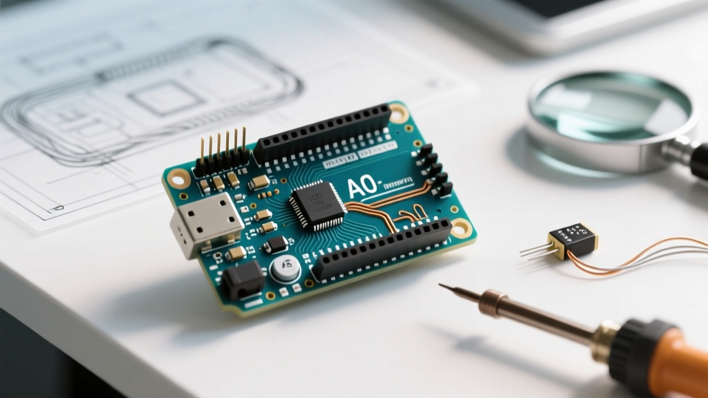

Understanding the Arduino ADC Architecture
The Arduino Analog-to-Digital Converter (ADC) is the critical bridge between real-world analog signals and your microcontroller's digital logic. Whether you are working with the classic ATmega328P on the Arduino Uno R3 (featuring a 10-bit successive approximation ADC) or the modern Renesas RA4M1 on the Uno R4 Minima (boasting a 14-bit ADC, typically mapped to 12-bit in the core), erratic analogRead() values can completely derail sensor calibration and PID control loops.
When your serial monitor spits out fluctuating values like 512, 519, 504, 521 for a static voltage, or when readings slowly drift over time, the issue rarely lies in the sensor itself. Instead, it stems from source impedance mismatches, reference voltage noise, multiplexer crosstalk, or improper prescaler configurations. This guide provides a deep-dive troubleshooting framework to isolate and fix Arduino ADC anomalies.
1. The Source Impedance Bottleneck
The most common cause of consistently low or drifting Arduino ADC readings is exceeding the maximum recommended source impedance. The ATmega328P ADC utilizes an internal sample-and-hold (S/H) circuit with a sampling capacitor (Csample) of approximately 14pF. During the acquisition phase, this capacitor must charge to the exact voltage of your input signal.
The Math Behind the Failure
To achieve true 10-bit accuracy, the S/H capacitor must charge to within half of a Least Significant Bit (LSB). This requires approximately 7.6 time constants ($\tau$). The time constant is calculated as:
$\tau = (R_{source} + R_{adc}) \times C_{sample}$
- Optimal Scenario (10kΩ Source): With a 10kΩ voltage divider, $\tau \approx 141$ nanoseconds. The required charging time is roughly 1.07 microseconds. Since the default ADC acquisition time is about 12 microseconds (at a 125kHz ADC clock), the capacitor charges fully.
- Failure Scenario (100kΩ Source): If you use high-value resistors (e.g., two 100kΩ resistors to monitor a 12V battery), $\tau$ jumps to 1.4 microseconds. The required charging time exceeds 10.6 microseconds. Add breadboard parasitic capacitance (often 2pF-5pF per node), and the S/H capacitor fails to charge fully before the conversion begins. The result? Readings that are artificially low and highly susceptible to noise.
Hardware Fixes for High Impedance
- Parallel Decoupling Capacitor: Solder or wire a 100nF (0.1µF) X7R ceramic capacitor directly between the analog input pin and GND. This creates a local charge reservoir, effectively dropping the AC source impedance to near zero during the sampling window.
- Op-Amp Buffer: For precision applications, buffer the signal using a low-offset, rail-to-rail operational amplifier like the MCP6001 (approx. $0.45 per unit in 2026). The op-amp presents a high impedance to your sensor and a near-zero output impedance to the Arduino ADC.
2. Power Supply Noise & AREF Configuration
If your ADC readings are highly noisy (jumping ±10 to ±20 bits), your voltage reference is likely the culprit. By default, the Arduino uses the 5V USB or barrel jack supply as the ADC reference (DEFAULT). PC USB ports are notoriously noisy, often carrying 50mV to 100mV of high-frequency switching ripple from the host's power supply. Because the ADC measures the ratio of the input voltage to the reference voltage, any noise on the 5V rail maps directly into your digital output.
Switching to the Internal Reference
The ATmega328P features an internal 1.1V bandgap reference. While not perfectly accurate across all chips (it can range from 1.0V to 1.2V), it is exceptionally stable and immune to USB power ripple. You can enable it in your setup function:
analogReference(INTERNAL); // Use 1.1V internal referenceNote: For the Uno R4 Minima (RA4M1), the internal reference options differ. Consult the Arduino Uno R4 Minima Cheat Sheet for specific RA4M1 voltage reference configurations.
Using an External Precision Reference (AREF)
For industrial or high-precision sensor nodes, bypass the internal references entirely. Connect a precision shunt voltage reference like the LM4040-4.1 (4.096V, ~$1.20) to the AREF pin. This provides a stable, low-noise baseline that perfectly aligns with binary math (4.096V / 1024 = exactly 4mV per bit).
CRITICAL WARNING: Never apply an external voltage to the AREF pin while your software is set to analogReference(DEFAULT). This will short the internal 5V VCC line directly to your external voltage source, potentially destroying the microcontroller's internal power routing. Always set the reference in software before powering the external AREF circuit.
3. Multiplexer Crosstalk: The "First Read" Anomaly
Microcontrollers do not have dedicated ADC hardware for every analog pin. Instead, they use an internal analog multiplexer (MUX) to route different pins to a single ADC core. If you read from A0, and then immediately read from A1, the first value returned from A1 will often be heavily skewed toward the voltage present on A0.
This happens because the S/H capacitor retains residual charge from the previous channel, and the internal MUX switches have finite on-resistance. If the source impedance on A1 is high, the capacitor cannot fully bleed off the A0 charge and adopt the A1 voltage within a single conversion cycle.
The Software Fix: Double Sampling
Whenever you switch analog pins, discard the first reading. This is a mandatory practice in robust firmware design.
// Correct way to read multiple analog pins
int readA0 = analogRead(A0);
delayMicroseconds(10); // Allow MUX to settle
int dummyA1 = analogRead(A1); // Discard first read
int readA1 = analogRead(A1);  // Keep second read
4. ADC Prescaler Tuning for Speed vs. Accuracy
The ADC requires a specific clock frequency to operate correctly. According to the Microchip ATmega328P Datasheet, the ADC clock must be between 50kHz and 200kHz to guarantee maximum 10-bit resolution. The Arduino core defaults to a prescaler of 128, dividing the 16MHz system clock down to 125kHz. This yields a safe, accurate, but relatively slow conversion time of roughly 104 microseconds per read.
If you are doing high-speed audio sampling or fast PID control, you can manipulate the ADC prescaler registers directly. However, pushing the ADC clock past 200kHz degrades the Signal-to-Noise Ratio (SNR) and effective number of bits (ENOB).
| Prescaler | ADC Clock (at 16MHz) | Conversion Time | Resolution Impact | Use Case |
|---|---|---|---|---|
| 128 (Default) | 125 kHz | ~104 µs | Full 10-bit guaranteed | Standard sensors, thermistors, potentiometers |
| 64 | 250 kHz | ~52 µs | Slight ENOB drop (~9.5 bit) | Faster control loops, moderate speed data logging |
| 32 | 500 kHz | ~26 µs | Noticeable noise, ~8-9 bit | Basic audio envelope detection, fast RMS |
| 16 | 1 MHz | ~13 µs | Severe degradation (~7 bit) | High-speed crude threshold detection only |
5. Software Oversampling: Pushing Past 10-Bit Limits
If your hardware is optimized but you still require finer granularity than the native 10-bit (1024 steps) resolution, you can use software oversampling. By taking multiple samples and applying a bit-shift, you can artificially increase the ADC resolution, provided there is at least 1 LSB of natural thermal noise in the system to dither the signal.
To gain n extra bits of resolution, you must sample $4^n$ times and divide the sum by $2^n$.
- 11-bit resolution: Sum 4 reads, divide by 2 (or right-shift by 1).
- 12-bit resolution: Sum 16 reads, divide by 4 (or right-shift by 2).
- 14-bit resolution: Sum 256 reads, divide by 16 (or right-shift by 4).
Performance Note: Generating a 12-bit read via oversampling on a 16MHz ATmega328P takes roughly 1.6 milliseconds. For the Renesas RA4M1 on the Uno R4, hardware-level 14-bit oversampling is natively supported via the Arduino analogRead() Reference by utilizing the analogReadResolution(14) function, bypassing the need for manual software accumulation.
6. Physical Layout & Ground Loop Mitigation
Finally, do not ignore the physical layer. Breadboards and long, unrouted jumper wires act as highly efficient antennas for electromagnetic interference (EMI), particularly the 50Hz/60Hz mains hum from nearby AC wiring.
- Twisted Pair Wiring: When routing analog signals from remote sensors (e.g., a PT100 RTD or a remote potentiometer), always use twisted pair cables. This ensures that induced magnetic noise is applied equally to both the signal and ground wires, allowing the ADC to reject it as common-mode noise.
- Star Grounding: If your project includes high-current components like DC motors or relays, never share the same ground return path for the motor and the analog sensors. The voltage drop across the ground wire ($V = I \times R$) will be interpreted by the ADC as a fluctuating signal. Run a dedicated ground wire from the sensor directly to the Arduino's GND pin (star topology).
- Shielding: For sub-millivolt measurements (like load cells amplified by an HX711, though the HX711 has its own dedicated ADC), enclose the analog front-end in a grounded metallic enclosure or use copper tape tied to the system ground to block capacitive coupling from nearby AC sources.
Summary Diagnostic Checklist
When facing Arduino ADC issues, follow this sequential diagnostic path:
- Check Impedance: Is the source >10kΩ? Add a 100nF bypass capacitor.
- Check Reference: Is USB noise causing jitter? Switch to
INTERNALor an external LM4040. - Check MUX Crosstalk: Are you reading multiple pins? Discard the first read after a channel switch.
- Check Grounding: Are motors or relays sharing the sensor ground? Implement star grounding.
By systematically addressing the hardware physics and software configuration of the ATmega328P ADC, you can transform erratic, unusable analog data into stable, high-precision measurements suitable for professional-grade embedded applications.