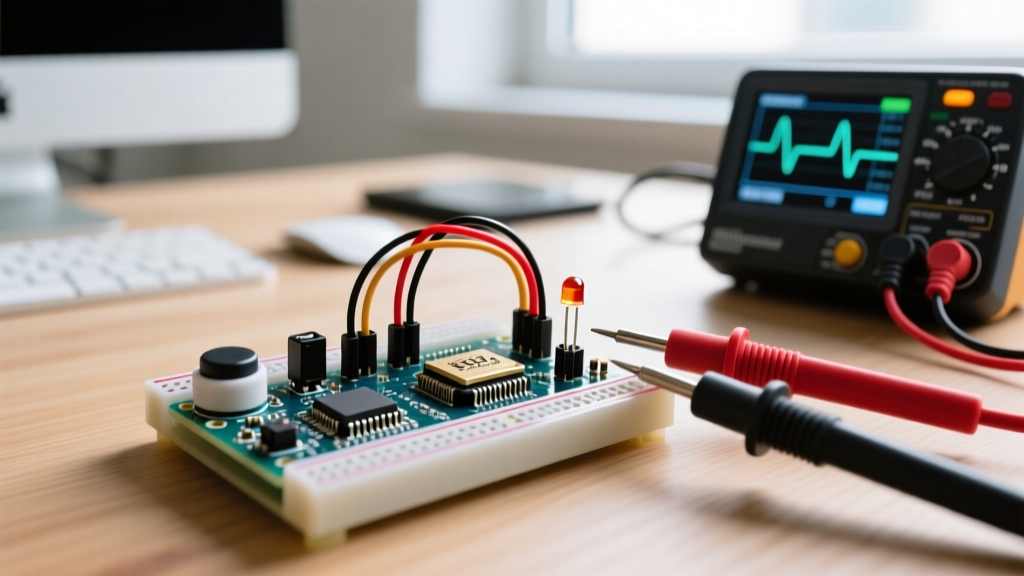

The Deceptive Simplicity of Digital Inputs
When building an on and off switch Arduino circuit, makers often assume that wiring a simple pushbutton or toggle switch to a digital pin is a trivial task. In theory, it is: close the circuit, read a HIGH or LOW, and trigger an action. In practice, the intersection of mechanical physics, CMOS electrical characteristics, and high-speed microcontroller polling creates a minefield of edge cases. If your Arduino is registering phantom presses, ignoring inputs, or toggling erratically, you are likely falling victim to one of four fundamental diagnostic failures.
This guide bypasses basic wiring tutorials and dives straight into advanced error diagnosis. We will use multimeter protocols, oscilloscope logic, and embedded C++ state-machine theory to isolate and resolve your switch failures.
Diagnostic Matrix: Identifying Your Switch Failure
Before rewriting your sketch or tearing apart your breadboard, map your symptoms to the diagnostic matrix below. This framework isolates whether your failure is rooted in hardware physics, electrical noise, or software logic.
| Symptom | Probable Root Cause | Multimeter / Scope Reading | Primary Solution |
|---|---|---|---|
| Random toggles without touching the switch | Floating Pin / EMI Interference | AC Voltage present (0.5V - 2.5V RMS) | Enable INPUT_PULLUP or add 10kΩ physical pull-down |
| Single press registers as 5-20 rapid triggers | Mechanical Contact Bounce | Square wave oscillation (1-20ms duration) | Implement software debouncing (e.g., Bounce2 library) |
| Switch works, but holding it down loops the action | Level-Reading vs. Edge-Detection Logic Error | Steady 5V (HIGH) or 0V (LOW) on the pin | Rewrite logic to detect state-change (edge) rather than state (level) |
| Intermittent failures, works when touched with finger | High Contact Resistance / Breadboard Fatigue | Voltage drop > 0.2V across closed switch | Replace tactile switch (e.g., C&K PTS645) or clean breadboard contacts |
Failure 1: The Floating Pin Phenomenon
The most common reason an on and off switch Arduino project behaves erratically is the floating input. The ATmega328P (used in the Uno R3 and Nano) and the ESP32 feature CMOS (Complementary Metal-Oxide-Semiconductor) digital inputs. These pins have an extraordinarily high input impedance, typically around 100 Megaohms.
When your switch is open (disconnected), the pin is not reading "zero"; it is reading the ambient electromagnetic environment. It acts as a tiny antenna, picking up 60Hz mains hum from nearby power cables, static electricity, and even the electrical noise generated by the Arduino's own switching voltage regulators. According to the Arduino Digital Pins Documentation, an unconnected pin can fluctuate wildly between HIGH and LOW.
The Fix: Internal vs. External Pull Resistors
To anchor the pin to a known voltage state when the switch is open, you must use a pull resistor.
- Internal Pull-Up (Recommended): In your
setup(), usepinMode(buttonPin, INPUT_PULLUP);. This activates an internal 20kΩ to 50kΩ resistor tied to 5V. Wire your switch between the digital pin and GND. The pin reads HIGH when open, and LOW when pressed. This requires zero extra components. - External Pull-Down: If your logic strictly requires the pin to be LOW when open and HIGH when pressed, you must wire a 10kΩ carbon film resistor between the digital pin and GND. The switch then connects the pin to 5V. Do not use values higher than 10kΩ for pull-downs, as the leakage current may fail to pull the pin fully to ground in noisy environments.
Failure 2: Mechanical Contact Bounce
When you press a mechanical switch, the metal contacts do not simply meet and stop. They physically collide, bounce apart, and collide again microscopically before settling. This phenomenon, known as contact bounce, occurs over 1 to 20 milliseconds. While imperceptible to humans, an Arduino Uno executing at 16 MHz can run tens of thousands of instructions in that timeframe, interpreting a single physical press as a rapid-fire burst of 50 separate button presses.
As detailed in Jack Ganssle's authoritative Guide to Debouncing, ignoring bounce will destroy the user experience of any toggle-based project, causing lights to flicker unpredictably or menus to scroll past their targets.
Hardware Debouncing (RC Filter)
If you want to solve bounce in hardware, place a 100nF (0.1µF) ceramic capacitor in parallel with the switch, combined with a 10kΩ resistor in series with the signal line. This creates a low-pass RC filter with a time constant (τ) of 1 millisecond. The capacitor absorbs the high-frequency bounce spikes, presenting a clean, albeit slightly sloped, voltage curve to the Arduino's Schmitt trigger input.
Software Debouncing (The Bounce2 Library)
For most makers, software debouncing is preferred as it saves component costs and board space. Avoid using delay() to wait out the bounce, as this halts the microcontroller and breaks real-time operations. Instead, use the industry-standard Bounce2 library. It tracks the time of the last state change and ignores subsequent transitions until the debounce window (typically 20ms) has elapsed.
Failure 3: Level-Reading vs. Edge-Detection Logic
A frequent error diagnosis scenario involves a user complaining: "My on and off switch Arduino code works, but if I hold the button down, the LED keeps flashing or the relay keeps clicking."
This is not a hardware failure; it is a fundamental logic error. The sketch is reading the level of the pin (is it currently HIGH?) rather than the edge (did it just transition from LOW to HIGH?).
Implementing State-Change Detection
To fix this, you must store the previous state of the switch and compare it to the current state. An action should only trigger when the current state differs from the previous state, and specifically when it matches your target transition.
Expert Tip: Always update your
lastButtonStatevariable at the very end of yourloop()function. If you update it prematurely, or only update it inside anifstatement, your edge-detection logic will desync and fail on rapid successive presses.
Hardware Verification: Multimeter Testing Protocol
When software fixes fail, you must verify the physical integrity of your circuit. Cheap tactile switches and fatigued breadboards are notorious for introducing contact resistance. Follow this strict diagnostic protocol using a digital multimeter (DMM):
- Continuity Test (Power Off): Set your DMM to continuity mode. Place probes on the switch terminals. Press the button. You should hear an immediate tone. If the tone stutters or delays, the internal leaf spring is oxidized or damaged. Replace the switch with a high-quality alternative, such as the C&K Components PTS645 series.
- Voltage Drop Test (Power On): Set your DMM to DC Voltage. Wire the switch to 5V and GND through a load (like an LED and resistor). Place the red probe on the 5V side of the switch and the black probe on the output side. Press the switch. A healthy switch will show a voltage drop of less than 0.05V. If you read 0.5V or higher, the internal contacts are degrading, acting as a voltage divider, and failing to deliver a logic HIGH to the Arduino.
- Breadboard Integrity: If using a solderless breadboard, insert a jumper wire into the same row as your switch leg. Measure continuity from the jumper wire to the switch leg. Breadboard leaf clips lose tension after repeated use, creating intermittent open circuits that mimic switch bounce.
Advanced Edge Cases: Long Wire Runs and EMI
If your on and off switch Arduino setup involves placing the physical switch more than 1 meter (3 feet) away from the microcontroller, standard pull-up resistors will fail. Long unshielded wires possess inherent parasitic capacitance and act as highly efficient antennas for Electromagnetic Interference (EMI).
When the switch opens, the 20kΩ internal pull-up resistor is too weak to quickly charge the parasitic capacitance of the long wire, resulting in a slow voltage rise time. The Arduino may read this slow rise as multiple transitions, or the wire may pick up enough RF noise from nearby Wi-Fi routers or fluorescent lights to cross the logic threshold.
Solutions for Remote Switching
- Lower the Pull-Up Resistance: For wire runs between 1 and 3 meters, disable the internal pull-up and install a physical 1kΩ to 4.7kΩ pull-up resistor at the Arduino pin. This provides a stronger current source to overcome wire capacitance.
- Use Twisted Pair Cable: Route your signal wire and ground wire as a twisted pair (e.g., using CAT5e Ethernet cable). This ensures that any ambient magnetic interference induces common-mode noise, which is rejected by the Arduino's input buffer.
- Optocoupler Isolation: For industrial environments or runs exceeding 5 meters, abandon direct wiring. Use an optocoupler (like the PC817) at the Arduino end, and drive the remote switch with a higher voltage (12V or 24V) to vastly improve the signal-to-noise ratio.
Component Selection Matrix for Maker Projects
Not all switches are created equal. Selecting the wrong mechanical component for your specific environment guarantees future diagnostic headaches. Consult the SparkFun Switch Basics Guide for foundational knowledge, and use the matrix below for 2026 project planning:
| Switch Type | Typical Bounce Time | Best Use Case | Known Failure Mode |
|---|---|---|---|
| 6x6mm Tactile (SPST) | 2 - 10ms | PCB mounted user inputs, reset buttons | Oxidation in high humidity; plastic stem snapping |
| SPDT Toggle Switch | 1 - 5ms | Master power, mode selection, state retention | Mechanical wear on the internal ball detent |
| Magnetic Reed Switch | < 1ms | Door/window sensors, non-contact limit switches | Glass envelope shattering from mechanical shock |
| Capacitive Touch (TTP223) | 0ms (Electronic) | Sealed enclosures, waterproof interfaces | False triggers from water droplets or thick acrylic |
Summary
Troubleshooting an on and off switch Arduino circuit requires looking past the basic wiring diagram. By systematically eliminating floating pins via INPUT_PULLUP, neutralizing mechanical bounce with the Bounce2 library, rewriting logic for edge-detection, and verifying contact resistance with a multimeter, you can transform an unreliable prototype into a robust, production-ready interface. Always respect the physics of the hardware, and your digital logic will follow suit.