
The Architecture of Arduino Serial to Serial Communication
Connecting two microcontrollers directly is a fundamental skill in embedded systems design. Whether you are offloading sensor polling to a secondary board, building a modular robotics rover, or bridging an isolated telemetry system, mastering arduino serial to serial communication via UART (Universal Asynchronous Receiver-Transmitter) is essential. Unlike I2C or SPI, which rely on a master-slave clock architecture, UART is asynchronous and point-to-point, making it incredibly resilient for long-distance wiring and cross-platform MCU integration.
In 2026, the maker ecosystem heavily features mixed-voltage environments. You are just as likely to connect a legacy 5V ATmega328P-based Arduino Nano to a modern 3.3V ESP32-S3 or Raspberry Pi Pico as you are to connect two identical boards. This tutorial provides a deep-dive, professional-grade approach to hardware wiring, voltage translation, and non-blocking code implementation to ensure zero packet loss between your nodes.
Hardware UART vs. SoftwareSerial: Choosing Your Interface
Before wiring a single jumper, you must select the correct serial peripheral. Relying on software-emulated serial can introduce severe timing jitter, especially at baud rates above 38400. According to the official Arduino Serial Reference, hardware UART is handled by dedicated silicon on the MCU, freeing the CPU for interrupt-driven tasks.
| Feature | Hardware UART (Serial1, Serial2) | SoftwareSerial Library |
|---|---|---|
| Max Reliable Baud | 1,000,000+ (Board dependent) | 115200 (High CPU overhead) |
| CPU Impact | Near zero (Interrupt driven) | High (Disables interrupts during TX/RX) |
| Pin Flexibility | Fixed to specific MCU pins | Any digital GPIO |
| Best Use Case | Primary MCU-to-MCU links, GPS, Cellular | Debugging, low-speed secondary sensors |
Expert Tip: If you are using an Arduino Mega 2560, utilize its three extra hardware ports (Serial1 on pins 18/19, Serial2 on 16/17, Serial3 on 14/15). If you are using an ESP32, remember that UART1 defaults to GPIO 9 and 10, which are often tied to the internal SPI flash. Always remap ESP32 UART1 or use UART2 to prevent boot crashes.
Physical Wiring and Voltage Level Shifting
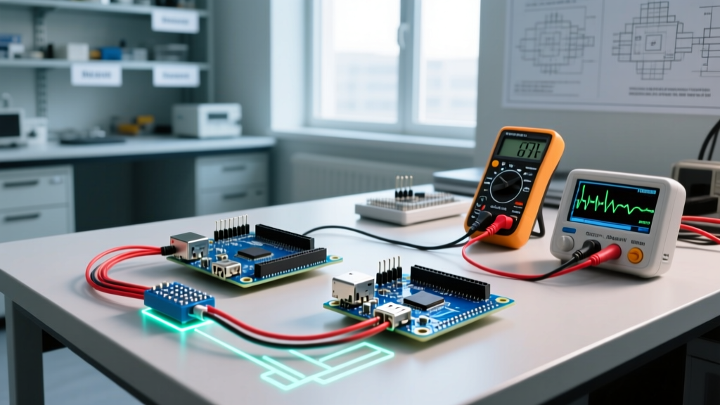
The most common point of failure in arduino serial to serial communication is ignoring logic level thresholds and common grounds. A serial link requires three physical connections:
- TX to RX: The Transmit pin of Board A must connect to the Receive pin of Board B.
- RX to TX: The Receive pin of Board A must connect to the Transmit pin of Board B.
- GND to GND: A shared ground reference is non-negotiable. Without it, the voltage differential floats, resulting in garbage data or complete link failure.
The 5V vs 3.3V Danger Zone
If you connect a 5V Arduino Uno directly to a 3.3V ESP32, the 5V logic high from the Uno's TX pin will backfeed into the ESP32's RX pin. Over time, this will degrade the ESP32's silicon and cause thermal throttling or permanent GPIO death. You must use a bi-directional logic level converter. The Texas Instruments TXB0108 or standard BSS138 MOSFET-based modules (available for roughly $1.50 to $3.00 on Amazon or DigiKey) safely translate the voltage rails. As noted in SparkFun's Serial Communication Tutorial, maintaining signal integrity across different voltage domains requires matching the baud rates precisely, as level shifters can introduce nanosecond-level propagation delays that compound at 1Mbps.
Step-by-Step Implementation: Sender and Receiver Code
Below is a robust, non-blocking implementation. We will use an Arduino Mega as the Sender (using Serial1) and an ESP32 as the Receiver (using Serial2 with remapped pins).
Sender Code (Arduino Mega 2560)
// Sender: Arduino Mega 2560 (5V Logic)
// Wiring: Mega TX1 (Pin 18) -> Level Shifter -> ESP32 RX

unsigned long lastTransmit = 0;
const unsigned long interval = 1000; // 1 second
int sensorValue = 0;

void setup() {
  Serial.begin(115200); // USB Debugging
  Serial1.begin(115200); // Hardware UART to ESP32
}

void loop() {
  if (millis() - lastTransmit >= interval) {
    lastTransmit = millis();
    sensorValue = analogRead(A0);

    // Frame the data with delimiters for robust parsing
    Serial1.print('<');
    Serial1.print(sensorValue);
    Serial1.print('>\n');
  }
}
Receiver Code (ESP32)
// Receiver: ESP32 (3.3V Logic)
// Wiring: ESP32 GPIO 16 (RX2) -> Level Shifter -> Mega TX

#define RXD2 16
#define TXD2 17
String incomingData = "";
bool receiving = false;

void setup() {
  Serial.begin(115200); // USB Debugging
  // Remap Serial2 to safe GPIO pins
  Serial2.begin(115200, SERIAL_8N1, RXD2, TXD2);
}

void loop() {
  while (Serial2.available() > 0) {
    char c = Serial2.read();

    if (c == '<') {
      receiving = true;
      incomingData = ""; // Clear buffer
    } else if (c == '>') {
      receiving = false;
      Serial.print("Parsed Sensor Value: ");
      Serial.println(incomingData.toInt());
    } else if (receiving) {
      incomingData += c;
    }
  }
}
Advanced Framing and Buffer Management
Beginners often use Serial.readString(), which is a blocking function that halts the MCU until a timeout occurs. In a real-time control loop, a 1000ms timeout is unacceptable. The code above utilizes a non-blocking state machine driven by Serial.available().
Furthermore, understanding the hardware ring buffer is critical. On standard AVR Arduinos, the hardware serial buffer is exactly 64 bytes. If your sender transmits a 100-byte JSON payload and your receiver's main loop is bogged down by a delay() or heavy I2C sensor polling, the buffer will overflow, and the oldest 36 bytes will be silently overwritten and lost. Always keep your loop() execution time under 5 milliseconds when expecting high-speed serial bursts, or implement DMA (Direct Memory Access) if you graduate to STM32 or advanced ESP32 frameworks.
Troubleshooting Edge Cases and Failure Modes
Even with perfect wiring, environmental and hardware quirks can disrupt arduino serial to serial communication. Here is how to diagnose the most stubborn issues:
- Garbage Characters in Terminal: This is almost always a baud rate mismatch. However, if both are set to 9600, check your oscillator. Cheap $3.50 ATmega328P clones often use internal resonators instead of external quartz crystals, which can drift by 2-5%. This drift causes bit-sampling errors at higher baud rates. Drop the baud rate to 4800 or 9600 for resonator-based clones.
- Intermittent Disconnects over Long Wires: UART was designed for short PCB traces. If your wires exceed 50cm, the lines act as antennas, picking up EMI (Electromagnetic Interference). Switch to RS-485 transceivers (like the MAX485) for differential signaling over distances up to 1200 meters.
- ESP32 Boot Failures: If your ESP32 fails to boot or enters a boot loop when wired to an Arduino, ensure the Arduino's TX pin isn't pulling the ESP32's RX pin (often GPIO 3 or GPIO 16) high or low during the ESP32's power-on sequence. The ESP32 strapping pins dictate boot modes; use a 10kΩ pull-up resistor on the RX line to stabilize the boot state.
By respecting voltage domains, utilizing hardware UART peripherals, and implementing non-blocking delimiter-based parsing, your multi-microcontroller projects will achieve industrial-grade reliability.