
Mastering Error Diagnosis on the Arduino Nicla Vision
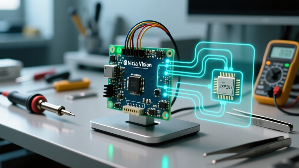
The Arduino Nicla Vision (Model ABX00051) represents a paradigm shift in edge machine vision. Packing a dual-core STM32H747 microcontroller, a GalaxyCore GC2145 2MP camera, a VL53L1X Time-of-Flight (ToF) sensor, and an LSM6DSOX 6-axis IMU into a footprint smaller than a postage stamp, it is an engineering marvel. However, this extreme density introduces complex failure modes that standard Arduino troubleshooting guides simply do not cover.
When working at the intersection of high-speed MIPI camera interfaces, dual-core memory arbitration, and MicroPython/OpenMV environments, a simple 'board not responding' error can stem from power rail brownouts, I2C bus contention, or firmware partition corruption. This guide provides deep-level diagnostic frameworks for resolving the most persistent Arduino Nicla Vision errors encountered in industrial and advanced maker deployments.
1. Power Delivery Brownouts and the 'Dead Board' Syndrome
The most frequently misdiagnosed issue with the Nicla Vision is a boot loop or a completely unresponsive board when the camera is initialized. This is rarely a defective MCU; it is almost always a transient voltage drop.
The Current Spike Problem
The STM32H747 features a Cortex-M7 core running at 480MHz and a Cortex-M4 at 240MHz. During idle states, the board draws roughly 85mA. However, the exact moment the GC2145 camera sensor initializes its internal Phase-Locked Loop (PLL) and begins streaming via the MIPI CSI-2 interface, current draw spikes to approximately 240mA–260mA.
If you are powering the board via a standard USB 2.0 port or a low-quality USB-C cable with high AWG (thin) wiring, the voltage at the board's USB-C receptacle can momentarily drop below 4.2V. The Nicla Vision's internal 3.3V LDO and switching regulators require adequate headroom. When the input voltage sags, the 3.3V rail dips below the STM32H747's Brownout Reset (BOR) threshold (typically 2.7V), instantly resetting the MCU before the OpenMV IDE can register the connection.
Critical Diagnostic Step: Do not rely on your PC's USB port for heavy vision workloads. Use a USB-C power meter inline with your cable to monitor voltage under load. If the 5V rail drops below 4.6V during camera initialization, switch to a regulated 5V/3A USB-C power supply or power the board via the VIN pin (3.6V to 5V) using a dedicated bench supply.
2. OpenMV IDE Connection Drops and Firmware Mismatches
The Nicla Vision is designed to bridge the Arduino IDE (using the Mbed OS core) and the OpenMV IDE (using MicroPython). A common error occurs when users flash an Arduino sketch that takes control of the USB CDC interface, and subsequently attempt to connect via OpenMV IDE, resulting in a Failed to connect to MicroPython board timeout.
Resolving the Dual-Environment Conflict
Unlike standard Arduino boards, the Nicla Vision partitions its 2MB flash memory to accommodate both the Mbed OS bootloader and the MicroPython filesystem. If an Arduino sketch corrupts the USB descriptors or enters a hard fault loop, the board will not enumerate as a MicroPython drive.
The DFU Recovery Protocol:
- Force Bootloader Mode: Connect the board via USB-C. Rapidly double-tap the reset button (if accessible via your carrier board) or use the Arduino IDE's Tools > Burn Bootloader command if you have an external SWD programmer attached to the test pads.
- Use the OpenMV Firmware Tool: Open the OpenMV IDE, navigate to Tools > Run Bootloader. This utilizes the STM32H747's native USB DFU (Device Firmware Upgrade) mode, bypassing the corrupted application layer entirely.
- Flash the Specific Nicla Build: Ensure you are flashing the exact firmware binary compiled for the ABX00051 hardware. Generic OpenMV H7 firmware will brick the camera interface due to differing pin multiplexing configurations.
For comprehensive recovery procedures, always refer to the Arduino Firmware Recovery Guide to ensure you are using the correct DFU utilities for the STM32H7 architecture.
3. Camera Initialization Failures (GC2145 Sensor)
When running vision scripts, encountering an OSError: Sensor control failed or RuntimeError: Camera Init Failed indicates a breakdown in communication between the STM32H747 and the GC2145 image sensor.
Investigating the XCLK and I2C Configuration
The GC2145 requires a precise external clock (XCLK) to operate its internal timing generators. On the Nicla Vision, this is typically driven at 24MHz by the STM32's internal clock output (MCO) pins. If the Mbed OS core or MicroPython firmware misconfigures the STM32's PLL, the XCLK frequency drifts, causing the sensor to reject I2C configuration commands.
Furthermore, the camera is configured via an I2C control bus (distinct from the MIPI data lanes). If you are attaching external I2C sensors to the Nicla's exposed I2C pins, you must account for bus capacitance. The onboard pull-up resistors are 4.7kΩ. Adding external modules with their own 2.2kΩ pull-ups drops the parallel resistance to ~1.5kΩ. This increases the current sink requirement on the STM32's open-drain pins, degrading the I2C rise times and causing the camera configuration sequence to time out.
- Fix: Remove external pull-up resistors on any breakout boards connected to the Nicla Vision's I2C bus.
- Fix: Verify the MIPI CSI-2 trace integrity. While the camera is integrated, severe thermal cycling in industrial enclosures can cause micro-fractures in the PCB vias connecting the MIPI lanes to the BGA pads of the STM32H747.
4. I2C Address Collisions: ToF and IMU Contention
The Nicla Vision shares its primary I2C bus with the VL53L1X ToF sensor (default address 0x29) and the LSM6DSOX IMU (default address 0x6A). A frequent edge case occurs when a user attempts to initialize an external I2C device that shares an address with the onboard sensors, or when a bus lockup occurs due to a missing ground reference on an external peripheral.
If the VL53L1X throws an I2C Timeout error in your Python script, it is often because the LSM6DSOX has entered a fault state and is holding the SDA line low.
Hardware Reset via XSHUT
To recover the ToF sensor without power-cycling the entire board, you can toggle its hardware reset pin. According to the Arduino Nicla Vision Hardware Documentation, the VL53L1X's XSHUT (shutdown) pin is mapped to a specific GPIO on the STM32. Driving this pin LOW for 100ms, then HIGH, forces the ToF sensor to reboot and clear its I2C state machine, resolving the bus lockup without affecting the camera or IMU.
Diagnostic Matrix: Common Errors and Solutions
Use the following matrix to rapidly isolate the root cause of your Nicla Vision failures.
| Error Symptom / IDE Output | Probable Root Cause | Diagnostic Action & Resolution |
|---|---|---|
Board not found / USB Disconnects on Camera Start |
5V Rail Brownout during MIPI PLL spin-up. | Measure USB voltage under load. Use a 5V/3A PSU or feed 4.5V directly to VIN. |
OSError: Sensor control failed |
I2C bus contention or XCLK frequency drift. | Remove external I2C pull-ups. Re-flash Nicla-specific OpenMV firmware via DFU. |
Failed to connect to MicroPython board |
Mbed OS sketch overriding USB CDC descriptors. | Enter DFU mode via double-tap or SWD. Use OpenMV IDE 'Run Bootloader' tool. |
VL53L1X I2C Timeout |
SDA line held low by IMU or external device. | Toggle VL53L1X XSHUT pin via GPIO. Check external device ground connections. |
Hard Fault / Flashing Red LED |
Memory protection unit (MPU) violation or bad pointer in C++ Mbed code. | Connect ST-Link V2 to SWD pads. Use STM32CubeIDE to read the fault trace address. |
Advanced Debugging: Leveraging the Dual-Core Architecture
For users writing custom C++ firmware via the Arduino IDE using the Mbed OS core, the dual-core nature of the STM32H747 can introduce obscure concurrency bugs. The Cortex-M7 handles the high-level logic and camera DMA (Direct Memory Access), while the Cortex-M4 is often relegated to DSP (Digital Signal Processing) tasks or sensor fusion.
If your board enters a HardFault_Handler loop, standard Serial.print debugging will fail because the USB stack resides on the M7 core, which is currently halted. To diagnose this, you must utilize the Serial1 (hardware UART) pins to output the fault registers, or connect an SWD debugger (like a J-Link or ST-Link V2) to the exposed SWDIO, SWCLK, and SWO test pads on the underside of the Nicla Vision PCB. Reading the OpenMV Nicla Vision Board Reference provides the exact memory map and pinmux configurations required to set up trace logging via the SWO pin, allowing you to capture the exact instruction address that triggered the memory violation.
Final Thoughts on Edge Vision Reliability
The Arduino Nicla Vision is an uncompromising piece of hardware, but it demands uncompromising power delivery and bus management. By shifting your diagnostic focus from simple code syntax to hardware-level realities—such as transient current spikes, I2C capacitance, and DFU partition management—you can transform the Nicla Vision from a temperamental prototype into a robust node for industrial machine vision and edge AI deployments.