
Why Your Arduino Button is Acting Erratic
Learning how to connect a button to Arduino is a rite of passage for every maker. Yet, it remains one of the most common sources of frustration in embedded projects. You wire up a simple 6x6mm tactile switch, upload your sketch, and instead of a clean trigger, your serial monitor spams garbage data, the pin triggers when you wave your hand near it, or a single press registers as five distinct events.
As of 2026, with the maker community heavily utilizing both 5V boards like the Arduino Uno R4 Minima and 3.3V ecosystems like the ESP32-S3, hardware wiring mistakes and logic-level mismatches are more common than ever. This troubleshooting guide bypasses the basic 'Hello World' tutorials and dives straight into the electrical engineering realities of switch debouncing, floating pin states, and GPIO architecture limitations.
The #1 Culprit: Floating Pins and the Antenna Effect
If your button triggers randomly without being touched, you are dealing with a floating pin. When a microcontroller GPIO pin is configured as an input but is not physically tied to a known voltage (HIGH or LOW), its impedance is nearly infinite. In this state, the copper trace on your breadboard acts as an antenna, picking up electromagnetic interference (EMI) from nearby AC mains wiring, switching power supplies, or even the static charge from your finger.
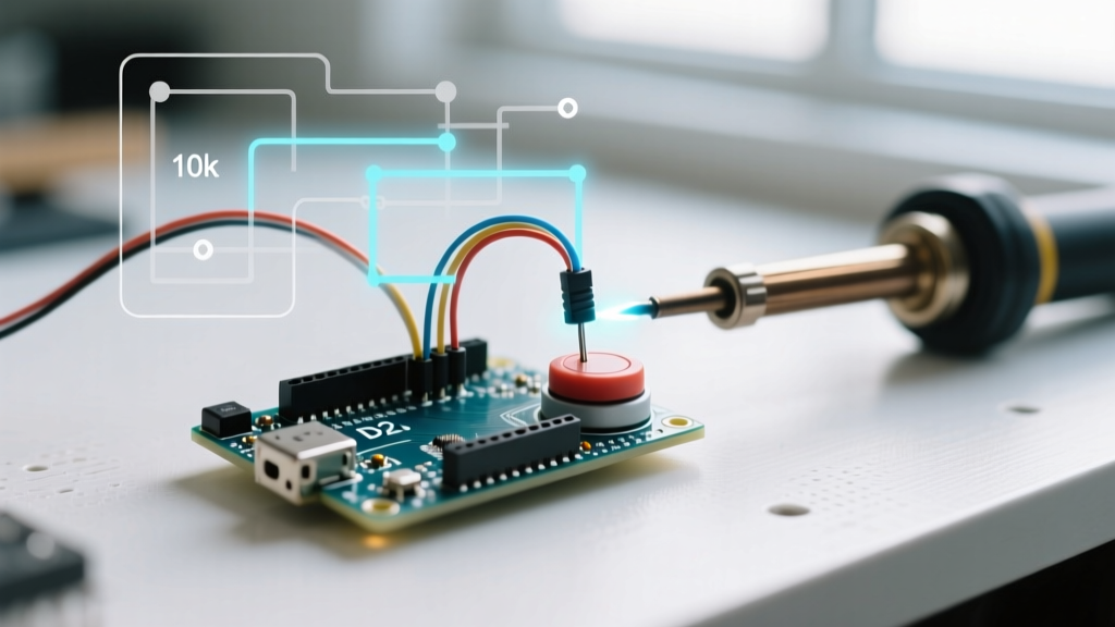
To fix this, you must use a pull resistor. You have two primary architectural choices:
| Configuration | Wiring Topology | Arduino Code Setup | Active State Logic | Best Use Case |
|---|---|---|---|---|
| Internal Pull-Up | Switch between Pin and GND | pinMode(pin, INPUT_PULLUP); |
LOW when pressed | 90% of standard DIY projects; saves board space. |
| External Pull-Down | 10kΩ resistor to GND; Switch to 5V/3.3V | pinMode(pin, INPUT); |
HIGH when pressed | Required for specific boot-strapping pins or legacy shields. |
| External Pull-Up | 10kΩ resistor to VCC; Switch to GND | pinMode(pin, INPUT); |
LOW when pressed | Mandatory for input-only pins lacking internal resistors. |
Expert Insight: Always default to the internal pull-up configuration. It requires only two wires (Pin and GND) and eliminates the need for breadboard resistors. For a deeper dive into the silicon-level mechanics, review the official Arduino pinMode() documentation.
Hardware Wiring Faults: NO vs. NC and the 4-Pin Trap
The standard 6x6mm through-hole tactile switch has four legs. Makers frequently wire across the wrong axis, resulting in a circuit that is either permanently closed or permanently open. Internally, legs on the same side of the switch are shorted together. You must wire diagonally across the switch body to cross the internal mechanical gap.
The Multimeter Continuity Test
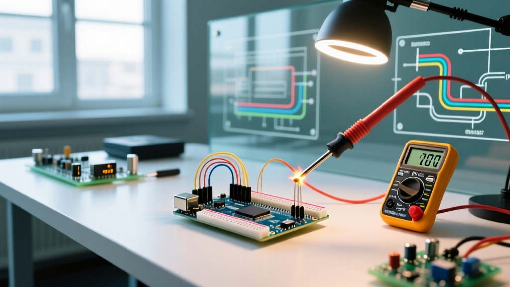
Before applying power to your microcontroller, grab a multimeter (even a basic $15 DT830B works perfectly) and set it to continuity mode (the diode/sound symbol).
- Place one probe on leg 1 and the other on leg 2 (same side). You should hear a continuous beep. These are internally jumpered.
- Move the probe to leg 3 (opposite side). The meter should read 'OL' (Open Loop) or infinite resistance.
- Press the button cap. The meter should now beep, confirming the Normally Open (NO) mechanical bridge is closing.
Panel Mount Switches: If you are using a chassis-mounted momentary switch with screw terminals, you will typically see three terminals: C (Common), NO (Normally Open), and NC (Normally Closed). For standard Arduino triggering, wire your GPIO to C and your GND to NO. Wiring to NC will invert your logic and can cause boot-loop issues if the pin is read during the microcontroller's initialization phase.
The Ghost Press: Diagnosing and Fixing Switch Bounce
Mechanical switches do not make clean electrical contact. When the metal contacts slam together, they physically bounce, creating a rapid series of make-and-break connections lasting anywhere from 1ms to 50ms. To a microcontroller executing millions of instructions per second, one physical press looks like 20 distinct button presses.
Hardware Debouncing (The RC Filter)
If you are designing a custom PCB or need hardware-level stability for interrupt-driven pins, use an RC (Resistor-Capacitor) low-pass filter.
- Components: 10kΩ pull-up resistor, 1kΩ series resistor, and a 100nF (0.1µF) X7R ceramic capacitor.
- Wiring: Wire the 10kΩ from VCC to the GPIO. Place the switch from GPIO to GND. Put the 100nF capacitor in parallel with the switch. Add the 1kΩ resistor in series between the switch and the GPIO to prevent the capacitor from discharging too rapidly and damaging the internal GPIO protection diodes.
Software Debouncing (The 2026 Standard)
For 95% of breadboard projects, software debouncing is preferred. Avoid using delay(50) to wait out the bounce; this blocks the main loop and ruins real-time sensor reading. Instead, utilize the Bounce2 library or a non-blocking millis() timer. As detailed in Jack Ganssle's legendary embedded systems guide, A Guide to Debouncing, tracking the state change over a 20ms window using non-blocking timers is the industry standard for reliable edge detection.
Logic Level Disasters: 5V vs. 3.3V Microcontrollers
A catastrophic failure mode occurs when makers transition from a 5V Arduino Uno to a 3.3V board like the ESP32 or Arduino Nano 33 IoT without adjusting their external wiring.
The ESP32 Input-Only Pin Trap
If you are trying to connect a button to an ESP32 and INPUT_PULLUP is not working, check your pin number. The original ESP32 and many ESP32-S3 variants feature specific GPIOs (typically GPIO 34, 35, 36, and 39 on the classic chip) that are strictly input-only.
These pins lack internal pull-up resistors in the silicon. If you configure them with INPUT_PULLUP, the compiler won't throw an error, but the pin will float, causing erratic behavior.
The Fix: You must solder or breadboard an external 10kΩ resistor from the GPIO to the 3.3V pin. Furthermore, never apply 5V to these pins via a pull-up resistor; doing so will backfeed the 3.3V rail and potentially destroy the SoC. For a comprehensive breakdown of GPIO limitations, consult the SparkFun Pull-Up Resistor Tutorial.
Master Troubleshooting Checklist
When your button circuit fails, run through this systematic diagnostic sequence to isolate the fault:
- Step 1: Verify the Active Logic. Are you using
INPUT_PULLUP? If so, your code must look forLOWto detect a press, notHIGH. - Step 2: Check the Axis. Rotate the tactile switch 90 degrees on the breadboard. You may be wired across the internally shorted legs.
- Step 3: Measure Voltage. Use a multimeter to probe the GPIO pin while pressing the button. It should swing cleanly from ~3.3V/5V down to 0.05V or less. If it only drops to 1.5V, you have a short circuit or a failing breadboard contact.
- Step 4: Inspect for Solder Bridges. If using a custom shield or perfboard, ensure no stray solder flux is creating a high-resistance bridge between the GPIO and VCC, fighting your pull-down resistor.
- Step 5: Rule out EMI. If the wire run from the button to the Arduino exceeds 12 inches, the wire is acting as an antenna. Switch to a shielded cable, lower the pull-up resistor to 4.7kΩ to increase the current drive and noise immunity, or add a hardware 100nF debounce capacitor at the pin.
By understanding the underlying electrical principles—impedance, mechanical bounce, and silicon-specific GPIO architectures—you transform from a hobbyist copying schematics into an embedded systems troubleshooter capable of diagnosing any switch interface failure.