
The Hidden Bottleneck in Analog Workflows
When prototyping microcontroller interfaces, the humble potentiometer is often treated as an afterthought. Makers grab a random dial from a bin, wire it to an analog pin, and write a quick analogRead() loop. Then the frustration begins: jittery values, ghost readings on adjacent pins, and UI inputs that refuse to hit exact zero or maximum thresholds. Optimizing your workflow around the arduino potentiometer 10k standard is not just about picking the right resistance; it is about aligning hardware physics, signal conditioning, and non-blocking firmware to eliminate hours of downstream debugging.
In 2026, with the proliferation of high-speed IoT MCUs alongside legacy 8-bit AVRs, understanding the precise electrical requirements of analog inputs is critical. This guide details a professional, repeatable workflow for integrating 10k ohm potentiometers into your Arduino projects, ensuring rock-solid stability from the breadboard to the final enclosure.
The Physics: Why 10kΩ is the AVR Gold Standard
To optimize your design workflow, you must first understand the internal architecture of the ATmega328P (and similar AVR chips) Analog-to-Digital Converter (ADC). The ADC uses a Successive Approximation Register (SAR) topology with an internal Sample and Hold (S&H) capacitor, typically around 14pF.
Engineering Insight: During the sampling phase, this internal capacitor must charge to the input voltage level within roughly 1.5 ADC clock cycles. If your source impedance is too high, the capacitor cannot fully charge, resulting in inaccurate reads and capacitive crosstalk between adjacent analog pins.
According to the official Arduino analogRead documentation, the recommended maximum source impedance is 10kΩ. Using a 100kΩ potentiometer might seem like a good way to save power, but it will force you to add software delays or hardware op-amp buffers to stabilize the signal, severely slowing down your development workflow. Sticking strictly to a 10kΩ linear taper potentiometer provides the perfect impedance match, allowing the internal S&H capacitor to charge almost instantaneously without external buffering.
Hardware Selection: Building a Reliable BOM
Not all 10k potentiometers are created equal. Cheap carbon-track potentiometers suffer from mechanical wear, wiper bounce, and severe thermal noise. For a streamlined workflow where you build it once and it works, upgrade your Bill of Materials (BOM).
Recommended Component Matrix
| Component Type | Model / Spec | Approx. Cost | Workflow Impact |
|---|---|---|---|
| Cermet Trimpot | Bourns 3386P-1-103LF | $1.15 - $1.40 | High lifecycle (200 cycles), low noise, ideal for internal calibration dials. |
| Panel Mount Pot | Bourns 91A1A-B28-B15L | $3.50 - $4.20 | Smooth torque, conductive plastic element, perfect for user-facing UI knobs. |
| Bypass Capacitor | Kemet 100nF X7R Ceramic | $0.10 | Eliminates high-frequency EMI before it reaches the ADC pin. |
Warning: Never use audio-taper (logarithmic) potentiometers for linear data mapping. Always verify the part number ends with a linear designation (e.g., 'B10K' or '103').
Wiring Workflow: Standardizing the Pinout
Inconsistent wiring is a primary cause of breadboard troubleshooting delays. Standardize your physical connections across all projects to build muscle memory and reduce schematic review time.
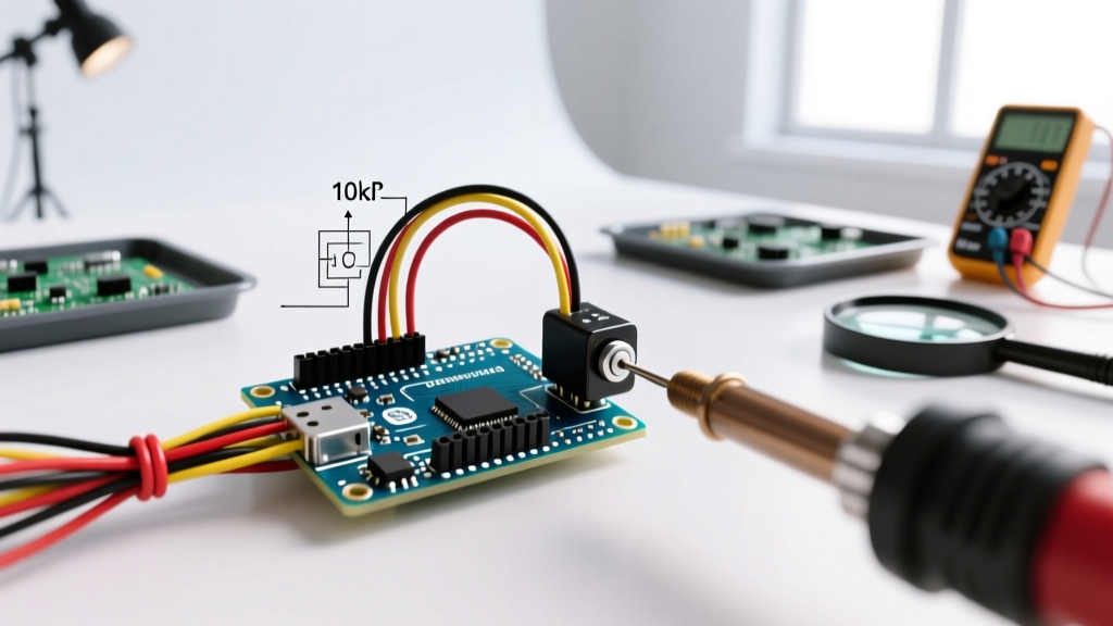
- Pin 1 (CCW): Connect to 5V (or 3.3V, matching your MCU logic level).
- Pin 2 (Wiper): Connect to the Analog Input (e.g., A0).
- Pin 3 (CW): Connect to GND.
- The Golden Rule: Solder or place a 100nF (0.1µF) ceramic capacitor directly between the Wiper (Pin 2) and GND. Place it as physically close to the MCU analog pin as possible. This creates a hardware low-pass filter that shunts high-frequency electromagnetic interference (EMI) to ground before the ADC samples it.
For a deeper dive into how ADCs process these analog signals, the SparkFun Analog-to-Digital Conversion tutorial provides excellent visual breakdowns of the sampling process and noise vulnerability.
Software Workflow: Non-Blocking Signal Conditioning
The default workflow for beginners involves reading the pin and using delay() to average out noise. This blocks the main loop, ruining real-time performance. The professional workflow utilizes an Exponential Moving Average (EMA) filter. This requires minimal memory, executes in microseconds, and provides buttery-smooth output without blocking.
Implementing the EMA Filter
Instead of a simple moving average that requires an array buffer, the EMA uses a recursive formula: Output = (Alpha * NewValue) + ((1 - Alpha) * PreviousOutput). An alpha value of 0.1 provides aggressive smoothing for noisy pots, while 0.5 offers a snappier response.
const int POT_PIN = A0;
const float ALPHA = 0.1; // Smoothing factor (0.0 to 1.0)
float smoothedValue = 0;

void setup() {
  Serial.begin(115200);
  analogReadResolution(10); // Explicitly set for 10-bit (0-1023) on modern cores
  smoothedValue = analogRead(POT_PIN); // Seed the filter
}

void loop() {
  int rawValue = analogRead(POT_PIN);

  // Apply Exponential Moving Average
  smoothedValue = (ALPHA * rawValue) + ((1.0 - ALPHA) * smoothedValue);

  // Implement Edge Clamping (Deadzones)
  int finalValue = (int)smoothedValue;
  if (finalValue < 15) finalValue = 0;
  if (finalValue > 1008) finalValue = 1023;

  Serial.println(finalValue);
  // No delay() used! Loop runs at maximum speed.
}
The Edge-Clamping Deadzone
Mechanical tolerances and ADC quantization mean your 10k pot might only physically output a range of 12 to 1015. Users hate it when a volume knob or brightness dial won't hit absolute 0% or 100%. By implementing a software deadzone (clamping values below 15 to 0, and above 1008 to 1023), you guarantee full range traversal, vastly improving the end-user experience without requiring precision hardware.
Calibration and Mapping Strategies
When mapping the 0-1023 range to real-world parameters (like motor PWM, servo angles, or RGB LED hues), avoid the basic map() function for critical applications. The standard map() function uses integer math, which truncates decimals and causes stepping artifacts.
Instead, use floating-point math for your scaling, then cast to an integer at the final step:
float normalized = smoothedValue / 1023.0; // Yields 0.000 to 1.000
int targetPWM = (int)(normalized * 255.0);
This guarantees a mathematically even distribution across your target range, eliminating the 'stutter' often seen in LED fades or motor accelerations driven by cheap potentiometers.
Troubleshooting Matrix: Rapid Diagnostics
When your analog input misbehaves, use this diagnostic matrix to identify the root cause in under 60 seconds, keeping your workflow moving.
| Symptom | Root Cause | Optimized Fix |
|---|---|---|
| Reading A0 changes the value on A1 | Source impedance too high; S&H cap crosstalk. | Verify pot is 10k, not 100k. Add 100nF cap to ground. |
| Values jump erratically by ±10 units | Carbon track noise or breadboard contact resistance. | Switch to Cermet/Conductive Plastic pot; solder joints instead of breadboard. |
| Max value caps at 980, never reaches 1023 | Voltage drop across long wires or breadboard rails. | Implement software deadzone clamping as shown in the EMA code block. |
| Readings are stuck at 1023 | Wired wiper to 5V, or internal trace broken. | Check Pin 2 continuity with a multimeter; verify pinout orientation. |
Understanding the fundamental behavior of variable resistors and voltage dividers is crucial for rapid diagnostics. The All About Circuits guide on potentiometers offers a fantastic refresher on the internal wiper mechanics and how they translate to voltage division.
Conclusion: Workflow as a Multiplier
Treating the arduino potentiometer 10k integration as a rigorous engineering step rather than a trivial wiring task pays massive dividends. By selecting low-noise cermet or conductive plastic components, standardizing your hardware pinouts with mandatory bypass capacitors, and deploying non-blocking EMA filters with edge clamping in your firmware, you completely eliminate the most common analog input bugs. This optimized workflow ensures that when you move from prototype to production, your analog interfaces remain responsive, stable, and mathematically precise.