
The I/O Bottleneck: Why Migrate from Direct Wiring?
Every maker eventually hits the same wall: the Arduino Uno or Nano runs out of analog pins. When your project evolves from reading a single potentiometer to polling an array of 12 soil moisture sensors or 16 thermistors, direct wiring becomes a physical and electrical nightmare. Daisy-chaining basic arduino multiplexer ICs is the standard solution, but as sensor density increases, the baseline CD74HC4051 (8-channel) often becomes the new bottleneck.
This migration guide is engineered for intermediate to advanced developers looking to upgrade their multiplexing architecture. We will cover the transition from the 8-channel 4051 to the 16-channel CD74HC4067, and finally, the paradigm shift to digital I2C multiplexing using the TCA9548A for modern sensor arrays.
Tier 1: Outgrowing the CD74HC4051 Baseline
The CD74HC4051 is the default entry point for analog multiplexing. It uses three digital select pins (S0, S1, S2) to route one of eight analog inputs to a common output pin. While adequate for small projects, it exhibits critical limitations in larger arrays:
- Pin Overhead: Multiplexing 16 sensors requires two 4051 ICs, consuming 6 digital select pins plus 2 analog read pins (if using separate common outputs to avoid crosstalk).
- On-Resistance ($R_{ON}$) Variance: At 5V, the $R_{ON}$ is roughly 120Ω, but if you migrate to a 3.3V microcontroller (like the Arduino Nano 33 IoT or ESP32), the $R_{ON}$ spikes to over 250Ω, causing severe voltage drops with low-impedance sensor loads.
- Breadboard Spaghetti: Routing VCC, GND, EN, and three address lines to multiple 4051s creates parasitic capacitance and crosstalk on unshielded breadboards.
Tier 2: The CD74HC4067 (16-Channel) Analog Migration
The most logical hardware upgrade is the CD74HC4067. This 16-channel analog multiplexer requires only four digital select pins (S0-S3) to address 16 distinct analog channels, routing them to a single common I/O pin.
Wiring and Addressing Logic
Migrating to the 4067 simplifies your physical footprint. You connect the common pin (Pin 1) to your Arduino's A0, and the four select pins (S0-S3) to digital pins D2 through D5. The Enable (EN) pin must be tied to GND to activate the IC.
Instead of using the notoriously slow digitalWrite() function to toggle the address pins—which takes roughly 4-5 microseconds per call in the Arduino AVR core—you should migrate your code to Direct Port Manipulation. This allows you to switch all four address pins simultaneously in a single clock cycle (62.5 nanoseconds on a 16MHz ATmega328P).
// Optimized 4067 Channel Switching via PORTD (Pins D2-D5)
void selectChannel(uint8_t channel) {
  // Clear bits 2-5 on PORTD, then apply the channel mask shifted by 2
  PORTD = (PORTD & 0xC3) | ((channel & 0x0F) << 2);
}
The ADC Sampling Delay Edge Case
A frequent failure mode during this migration is reading "ghost" voltages from the previous channel. The ATmega328P's internal ADC features a sample-and-hold capacitor (approx. 14pF). When the 4067 switches channels, this internal capacitor must charge through the multiplexer's $R_{ON}$ (120Ω) and the external wiring capacitance. If you are using long Cat5 cables (which add ~15pF per foot), the RC time constant increases. Actionable fix: Always insert a delayMicroseconds(150); immediately after switching the channel and before calling analogRead() to allow the internal capacitor to fully settle.
Tier 3: Digital Migration via TCA9548A I2C Multiplexer
If your 2026 project relies on modern environmental or inertial sensors (e.g., BME280, SCD40, MPU6050), analog multiplexers are useless. These sensors communicate via I2C. The problem? Most I2C sensors have hardcoded, unchangeable addresses. You cannot connect three BME280s to the same I2C bus; they will collide.
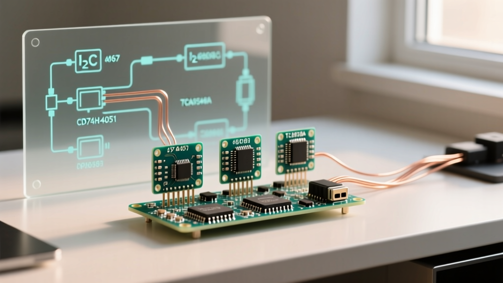
The migration path here is the TCA9548A I2C Multiplexer. Unlike the 4067, which passes analog voltages, the TCA9548A is a digital switch that routes the SDA and SCL lines to one of eight downstream I2C buses.
Solving the 400pF Bus Capacitance Limit
The I2C specification mandates a maximum bus capacitance of 400pF. When you wire multiple digital sensors in parallel, their combined pin capacitance and trace capacitance quickly exceed this limit, resulting in rounded signal edges and ACK/NACK failures. The TCA9548A solves this by isolating the capacitance. Only the currently selected downstream channel's capacitance is added to the main bus.
For a comprehensive implementation guide on pull-up resistor sizing and breakout wiring, refer to the Adafruit TCA9548A Tutorial. Remember that each of the 8 downstream channels requires its own set of 4.7kΩ pull-up resistors on SDA and SCL if the sensor breakout boards do not have them populated.
Component Comparison Matrix
| Feature | CD74HC4051 (8-Ch) | CD74HC4067 (16-Ch) | TCA9548A (8-Ch I2C) |
|---|---|---|---|
| Signal Type | Analog / Digital | Analog / Digital | Digital (I2C Only) |
| Select Pins Req. | 3 | 4 | 0 (Uses I2C Address) |
| Typical $R_{ON}$ (5V) | ~120Ω | ~120Ω | ~4Ω (MOSFET) |
| Raw IC Price (2026) | ~$0.65 (DIP) | ~$1.45 (DIP) | ~$1.80 (TSSOP) |
| Breakout Board Price | ~$5.00 | ~$10.95 (SparkFun) | ~$9.95 (Adafruit) |
| Best Use Case | Basic button pads, small pot arrays | Dense thermistor/soil moisture grids | Multiple identical I2C sensors |
PCB Layout Rules for High-Density Multiplexing
When migrating from a breadboard prototype to a custom PCB, multiplexed analog arrays require strict layout discipline to prevent digital noise from corrupting analog readings.
- Star Grounding: The analog ground (AGND) of your sensor array must be routed separately from the digital ground (DGND) of the multiplexer's select lines. Tie them together at a single star point near the microcontroller's power supply.
- Decoupling Capacitors: Place a 100nF (0.1μF) ceramic capacitor as close to the VCC pin of the 4067 or TCA9548A as physically possible. Switching 16 channels simultaneously causes high-frequency current spikes that will brown out the IC if decoupling is inadequate.
- Trace Routing: Never route digital address lines (S0-S3) parallel to the analog common output trace. If they must cross, force them to cross at a strict 90-degree angle to minimize capacitive crosstalk.
2026 Sourcing and Migration Economics
As of early 2026, the global semiconductor supply chain has stabilized, making raw DIP and SMD multiplexer ICs highly accessible. If you are building a one-off prototype, purchasing a SparkFun 16-channel analog breakout or an Adafruit TCA9548A breakout for ~$10 is the most time-efficient route. However, if you are migrating to a production run of 50+ units, buying raw TI CD74HC4067 DIP ICs from Mouser or DigiKey drops the cost to roughly $1.45 per unit, yielding massive savings despite the manual soldering overhead.
Upgrading your arduino multiplexer architecture is not just about adding more pins; it is about maintaining signal integrity, optimizing CPU cycles via port manipulation, and respecting the physical limits of bus capacitance. Choose the 4067 for dense analog arrays, and the TCA9548A for modern digital sensor networks.