
Beyond 'Hello World': The Engineering Behind the Blink
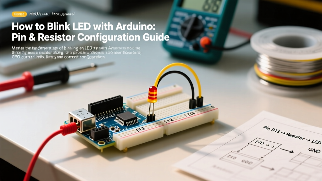
Learning how to blink LED with Arduino is universally recognized as the 'Hello World' of embedded systems. However, treating it merely as a copy-paste coding exercise leaves makers vulnerable to hardware damage and inefficient software architecture. In 2026, with the widespread adoption of the Arduino Uno R4 series and advanced IDE 2.x environments, understanding the precise electrical configuration and non-blocking software patterns of a simple LED circuit is foundational for scaling up to complex IoT and robotics projects.
This configuration guide bypasses the superficial tutorials and dives deep into the exact hardware sizing, microcontroller GPIO limits, and professional-grade firmware structures required to reliably blink an LED without degrading your board.
Hardware Configuration: Sizing the Current-Limiting Resistor
The most common point of failure for beginners is connecting an LED directly to a digital pin without a current-limiting resistor. An LED is a diode; once its forward voltage ($V_f$) threshold is crossed, its resistance drops to near zero, drawing maximum current until either the LED or the microcontroller's GPIO pin burns out.
The Math: Ohm’s Law for GPIO Pins
To configure the correct resistor, you must apply Ohm's Law: R = (Vcc - Vf) / I.
- Vcc: The logic voltage of your specific Arduino board (5V for Uno R3, 3.3V for Uno R4 WiFi or ESP32).
- Vf: The forward voltage drop of your specific LED color.
- I: The target current. Standard 5mm through-hole LEDs (like the widely used Kingbright WP7113SRD) are rated for 20mA continuous, but driving them at 10mA to 15mA provides nearly identical luminosity while drastically extending component lifespan and reducing thermal load on the MCU.
Resistor Sizing Matrix for Standard 5mm LEDs
| LED Color | Typical Vf | Target Current | Resistor (5V Logic / Uno R3) | Resistor (3.3V Logic / Uno R4 WiFi) |
|---|---|---|---|---|
| Red | 2.0V | 15mA | 200Ω (Use 220Ω standard) | 86Ω (Use 100Ω standard) |
| Yellow | 2.1V | 15mA | 193Ω (Use 220Ω standard) | 80Ω (Use 82Ω standard) |
| Green (Pure) | 3.2V | 15mA | 120Ω | Not recommended directly* |
| Blue / White | 3.4V | 15mA | 106Ω (Use 120Ω standard) | Not recommended directly* |
*Critical Edge Case: 3.3V logic boards cannot reliably drive Blue, White, or Pure Green LEDs directly because the Vcc is too close to the LED's Vf. The GPIO pin will not source enough current to illuminate the LED properly, resulting in a dim flicker. For 3.3V systems, configure an NPN transistor (like a 2N2222) or a MOSFET to switch the LED using a separate 5V rail.
Microcontroller Architecture: GPIO Limits and Pin Configuration
Not all Arduino boards are created equal. Configuring your pins requires knowing the absolute maximum ratings of the underlying silicon. According to the official Arduino Digital Pins documentation, exceeding these limits will permanently degrade the silicon junction.
ATmega328P (Uno R3) vs. Renesas RA4M1 (Uno R4 Minima)
The classic Arduino Uno R3 (priced around $27.00) uses the Microchip ATmega328P. This chip operates at 5V logic and can safely source or sink up to 20mA per pin, with an absolute maximum of 40mA. However, the total current across all VCC and GND pins must not exceed 200mA.
Conversely, the modern Arduino Uno R4 Minima (retailing for approximately $27.50) utilizes the Renesas RA4M1 ARM Cortex-M4 processor. This chip operates at 3.3V logic. Its GPIO pins have a much stricter absolute maximum rating of 8mA per pin. If you attempt to use a 100Ω resistor on a 3.3V R4 Minima to drive a blue LED, you risk pulling over 30mA, instantly frying the RA4M1's internal trace. Always configure higher value resistors (e.g., 470Ω) or use logic-level MOSFETs when migrating from 5V to 3.3V architectures.
Current Sourcing vs. Current Sinking
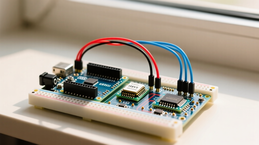
When wiring your breadboard, you have two configuration choices:
- Current Sourcing: The GPIO pin outputs HIGH (Vcc), current flows through the resistor and LED, and into GND. The MCU pin is 'supplying' the current.
- Current Sinking: The LED and resistor are connected to Vcc. The GPIO pin is set to LOW (GND). The MCU pin is 'absorbing' the current.
Historically, older 8-bit microcontrollers could sink more current than they could source. On modern ARM-based boards like the R4, sourcing and sinking capabilities are generally symmetrical, but sinking is often preferred in industrial PLC designs to keep the load tied to a constant positive rail, reducing EMI susceptibility.
Software Configuration: Non-Blocking Blink Architecture
The standard 'Blink' sketch uses the delay() function. In professional firmware development, delay() is considered an anti-pattern because it halts the CPU, preventing the microcontroller from reading sensors, handling serial communications, or managing wireless stacks.
To properly configure a blink routine for production, you must use a state-machine approach driven by the millis() timer.
// Non-blocking LED Blink Configuration
const int LED_PIN = 8;
const unsigned long BLINK_INTERVAL = 1000; // 1 second

unsigned long previousMillis = 0;
bool ledState = LOW;

void setup() {
  pinMode(LED_PIN, OUTPUT);
}

void loop() {
  unsigned long currentMillis = millis();

  // Check if the interval has passed
  if (currentMillis - previousMillis >= BLINK_INTERVAL) {
    previousMillis = currentMillis; // Save the last time you blinked

    // Toggle the state
    ledState = !ledState;
    digitalWrite(LED_PIN, ledState);
  }

  // The CPU is now free to execute other tasks here
  // e.g., readSensors(), updateDisplay(), handleWiFi()
}
This configuration ensures deterministic timing without blocking the main execution loop. Note the use of unsigned long for time variables; this prevents integer overflow errors that occur after approximately 49.7 days of continuous uptime, a common bug in poorly configured IoT devices.
Troubleshooting Common Configuration Failures
Even with the correct code, hardware misconfigurations frequently cause issues. Use this diagnostic matrix to resolve edge cases:
- Symptom: LED is extremely dim.
Cause: You are likely using a 3.3V board to drive a high-Vf LED (Blue/White), or your resistor value is too high.
Fix: Verify your board's logic level. If using 3.3V, switch to a Red LED or implement a transistor switching circuit. - Symptom: LED stays on but does not blink.
Cause: Pin conflict. You may have configured a pin that is internally tied to the onboard USB-to-Serial chip (like Pin 0 or 1 on the Uno R3).
Fix: Reconfigure your circuit to use Pins 2 through 12. - Symptom: Microcontroller resets randomly when LED turns on.
Cause: Voltage brownout. If you are driving multiple high-power LEDs or a relay alongside your indicator LED, the sudden current draw is causing the Vcc rail to dip below the MCU's brownout detection threshold.
Fix: Add a 100µF electrolytic decoupling capacitor across the 5V and GND rails on your breadboard to stabilize transient current demands. - Symptom: Pin outputs 1.5V instead of 0V when set to LOW.
Cause: Floating pin or missing ground reference. The ground of your external LED circuit is not tied to the Arduino's GND.
Fix: Ensure a common ground connection between the Arduino, the breadboard, and any external power supplies.
Summary and Next Steps
Learning how to blink LED with Arduino is the first step toward mastering embedded I/O. By correctly calculating your current-limiting resistors based on your specific board's logic voltage, respecting the absolute maximum current ratings of the underlying silicon, and implementing non-blocking millis() code structures, you transition from a hobbyist copying tutorials to an engineer designing robust firmware. As you expand your projects in 2026, apply these same rigorous configuration principles to relays, sensors, and motor drivers to ensure long-term reliability and hardware safety.