
The Ultimate Quick Reference for the Arduino Blink LED Sketch
The arduino blink led sketch is universally recognized as the 'Hello World' of microcontrollers. Whether you are unboxing a brand-new Arduino Uno R4 Minima or dusting off a classic Nano clone, getting an LED to blink verifies your toolchain, bootloader, and basic hardware I/O. However, as maker kits evolve in 2026, variations in board architecture (especially with ESP32 and RP2040 integrations) have introduced new edge cases that trip up beginners.
This FAQ and quick reference guide cuts through the fluff, providing exact pinouts, resistor calculations, and advanced non-blocking code structures to ensure your LED projects compile, upload, and illuminate perfectly.
Quick Reference: Built-In LED Pinouts by Board
Not all microcontrollers use Pin 13 for the onboard LED. If your code compiles but the board's built-in LED refuses to blink, check this hardware matrix first.
| Microcontroller Board | Built-In LED Pin | Logic Type | Notes & Edge Cases |
|---|---|---|---|
| Arduino Uno R3 / R4 Minima | 13 | Active HIGH | Standard 5V logic. Tied to onboard SCK. |
| Arduino Nano (Classic) | 13 | Active HIGH | Also features a power LED on pin 17 (internal). |
| Arduino Mega 2560 | 13 | Active HIGH | Identical behavior to Uno. |
| ESP32 DevKit V1 | 2 | Active HIGH | Pin 13 is tied to flash SPI; do not use for LED. |
| ESP8266 NodeMCU | 2 (D4) | Active LOW | Write LOW to turn ON. Write HIGH to turn OFF. |
| Raspberry Pi Pico (RP2040) | 25 (LED) | Active HIGH | Use 'LED' constant in Arduino IDE core. |
FAQ: Code, Timing, and IDE Troubleshooting
Why does my sketch compile but the LED stays solid ON or OFF?
This is the most common failure mode when migrating from an AVR-based Arduino to an ESP8266 NodeMCU. The NodeMCU's built-in blue LED is wired to GPIO 2, which is Active LOW. This means the LED turns ON when the pin reads 0V (LOW) and turns OFF when it reads 3.3V (HIGH).
The Fix: Invert your logic. Change digitalWrite(LED_BUILTIN, HIGH); to digitalWrite(LED_BUILTIN, LOW); for the 'ON' state. Alternatively, define a macro at the top of your sketch to handle the inversion automatically.
How do I change the blink speed without breaking my code?
The standard blink sketch uses the delay() function. The value inside the parentheses represents milliseconds. A delay(1000) equals a 1-second pause. To achieve a 5Hz blink (5 times per second), you need a total cycle time of 200ms. Set your ON delay to 100 and your OFF delay to 100.
Pro Tip: Never use
delay()if your sketch needs to read sensors or listen for Wi-Fi data simultaneously.delay()halts the CPU entirely, causing network stack timeouts on ESP32/RP2040 boards and missing button presses on AVRs.
What is the non-blocking alternative to delay()?
For production-grade firmware, use the millis() function. According to the official Arduino reference, millis() returns the number of milliseconds since the board began running the current program. By tracking the 'last blink time' and comparing it to the current time, you can blink an LED in the background while executing other logic.
unsigned long previousMillis = 0;
const long interval = 1000;

void loop() {
  unsigned long currentMillis = millis();
  if (currentMillis - previousMillis >= interval) {
    previousMillis = currentMillis;
    // Toggle LED state here
  }
  // Other non-blocking code runs here freely
}
FAQ: External LED Wiring & Hardware Specifics
How do I correctly wire a standard 5mm external LED?
Standard 5mm through-hole LEDs remain a staple in 2026 maker kits (typically costing $8-$12 for an assortment of 500+ units). They require a current-limiting resistor to prevent burning out the LED or the microcontroller's GPIO pin.
- Identify Polarity: The Anode (positive) is the longer leg. The Cathode (negative) is the shorter leg, situated on the side with the flattened plastic rim.
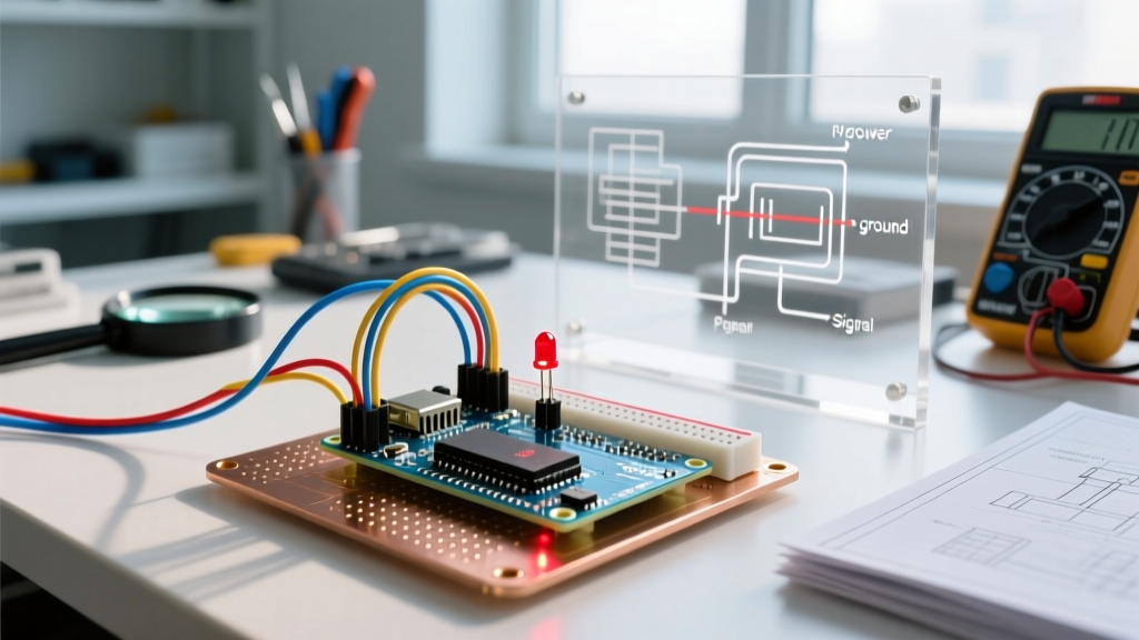
- Wire the Anode: Connect a jumper wire from your chosen digital pin (e.g., Pin 8) to one lead of a current-limiting resistor. Connect the other lead of the resistor to the Anode.
- Wire the Cathode: Connect the Cathode directly to the GND pin on your Arduino.
How do I calculate the exact resistor value I need?
Using Ohm's Law, the formula for the current-limiting resistor is: R = (Vs - Vf) / If.
Where Vs is source voltage (5V for Uno, 3.3V for ESP32), Vf is the LED forward voltage, and If is the desired forward current (typically 20mA or 0.02A for standard 5mm LEDs). As detailed in SparkFun's comprehensive LED guide, different colors have different forward voltages.
| LED Color | Typical Vf (Forward Voltage) | Resistor for 5V Source (Uno) | Resistor for 3.3V Source (ESP32) |
|---|---|---|---|
| Red | 2.0V | 150Ω (Use 220Ω standard) | 68Ω (Use 100Ω standard) |
| Yellow | 2.1V | 145Ω (Use 220Ω standard) | 60Ω (Use 100Ω standard) |
| Green | 2.2V | 140Ω (Use 220Ω standard) | 55Ω (Use 100Ω standard) |
| Blue / White | 3.2V - 3.4V | 90Ω (Use 100Ω standard) | Will not light reliably on 3.3V |
Hardware Warning: Blue and White LEDs require a minimum of 3.2V to 3.4V to overcome their forward voltage threshold. If you wire a blue LED directly to a 3.3V ESP32 GPIO pin, it will remain completely dark, even with correct code. Use a 5V logic level shifter or a transistor driver circuit for high-Vf LEDs on 3.3V boards.
Advanced Troubleshooting: Edge Cases & Failures
My external LED blinks, but it's incredibly dim. What's wrong?
If your wiring matches the standard Arduino Blink tutorial but the light output is weak, check these three culprits:
- Wrong Resistor Value: You may have accidentally grabbed a 10kΩ resistor (Brown-Black-Orange) instead of a 220Ω resistor (Red-Red-Brown). This restricts current to less than 1mA.
- GPIO Current Limits: Standard ATmega328P pins can safely source 20mA (absolute max 40mA). However, ESP32 and RP2040 pins often max out between 12mA and 16mA. If you are trying to pull 20mA from a 3.3V Pico pin, the voltage will sag, resulting in a dim LED.
- Counterfeit LEDs: Ultra-cheap bulk LEDs from unverified marketplaces often suffer from poor phosphor coating and high internal resistance. Stick to reputable suppliers like Adafruit, SparkFun, or DigiKey for critical projects.
Can I connect multiple LEDs to a single Arduino pin?
You can wire up to three standard red LEDs in series on a 5V Arduino Uno pin, provided you use a single 47Ω current-limiting resistor at the end of the chain (Total Vf = 2.0V + 2.0V + 2.0V = 6.0V. Wait, 6.0V exceeds the 5V source. Therefore, you can only wire two red LEDs in series on a 5V pin).
For parallel wiring, never share a single resistor across multiple parallel LEDs. Due to microscopic manufacturing variances, one LED will have a slightly lower Vf, hog all the current, burn out, and then cascade the failure to the remaining LEDs. Always use a dedicated resistor for each parallel LED branch, and ensure the total current draw does not exceed the microcontroller's per-pin or total-chip current limits.
Summary Checklist for a Successful Blink
Before assuming your board is defective, run this 4-point checklist:
- Verify the target board's specific built-in LED pin (13 for AVR, 2 for ESP32, 25 for Pico).
- Confirm Active HIGH vs. Active LOW logic for your specific clone board.
- Recalculate your resistor using Ohm's Law based on your exact board voltage (5V vs 3.3V) and LED color.
- Ensure your USB cable is rated for data transfer, not just power (a common reason for 'upload failed' errors masking as hardware failures).