
The Architecture of Arduino and FPGA Systems
Integrating an Arduino and FPGA into a single embedded system is a hallmark of advanced maker and engineering projects. While microcontrollers like the Arduino excel at sequential logic, high-level protocol management (USB, Wi-Fi, I2C), and user interface control, they are fundamentally limited by their single-threaded, instruction-cycle-based architecture. Field Programmable Gate Arrays (FPGAs), on the other hand, offer true hardware-level parallelism, making them ideal for high-speed digital signal processing (DSP), custom video pipelines, and simultaneous multi-channel ADC sampling.
By bridging these two architectures, you delegate the "heavy lifting" of parallel data processing to the FPGA, while the Arduino handles the "control plane"—managing network stacks, logging data to SD cards, and parsing user inputs. The most robust, high-speed, and reliable method to achieve this handshake in a maker environment is via the Serial Peripheral Interface (SPI) bus. This tutorial provides a comprehensive, expert-level guide to designing, wiring, and programming a high-speed SPI link between an Arduino and an FPGA, with a specific focus on avoiding the common pitfalls that plague beginner designs.
The 3.3V Logic Trap and Hardware Selection
The single most common failure mode when interfacing an Arduino and FPGA is logic level mismatch. The classic Arduino Uno (based on the ATmega328P) operates at 5V logic. Modern FPGAs, including Xilinx Artix-7 and Lattice iCE40 families, strictly utilize 3.3V, 2.5V, or even 1.8V I/O banks. Feeding a 5V signal directly into an FPGA I/O pin will permanently damage the silicon's clamping diodes, potentially destroying the chip.
While bidirectional logic level shifters (like the TXB0106) exist, they introduce propagation delays, capacitance, and signal integrity issues that severely limit SPI clock speeds to under 2 MHz. To achieve high-speed SPI (8 MHz to 24 MHz) without signal degradation, the optimal engineering decision in 2026 is to use a native 3.3V Arduino board.
Recommended Hardware Stack
For this tutorial, we are utilizing the Arduino Nano 33 IoT (featuring the 32-bit ARM Cortex-M0+ SAMD21 microcontroller) paired with the TinyFPGA BX (featuring the Lattice iCE40-LP8K FPGA). Both boards operate natively at 3.3V, eliminating the need for level shifters and preserving high-frequency signal integrity.
| Component | Model / IC | Approx. Price (2026) | Role in System |
|---|---|---|---|
| Microcontroller | Arduino Nano 33 IoT (SAMD21) | $24.00 | SPI Master, Network & Control Logic |
| FPGA Board | TinyFPGA BX (Lattice iCE40-LP8K) | $42.00 | SPI Slave, Parallel DSP Pipeline |
| Termination Resistors | 33Ω Through-Hole (1/4W) | $0.10 | Impedance matching / Ringing prevention |
| Pull-Up Resistor | 10kΩ Through-Hole | $0.10 | Chip Select (CS) line stabilization |
Hardware Wiring and Signal Integrity
When routing SPI traces over jumper wires on a breadboard, the wires act as inductive antennas. At 8 MHz, the square wave edges of the SPI clock (SCK) will exhibit severe "ringing" (voltage overshoot and undershoot) due to impedance mismatches and parasitic capacitance. This ringing can cause the FPGA to register false clock edges, resulting in corrupted data bytes.
Pinout and Wiring Matrix
Wire the boards according to the following matrix. Note the inclusion of series termination resistors on the source side of the unidirectional lines to dampen high-frequency reflections.
- Arduino 3.3V to FPGA 3.3V (Only if sharing a single PSU; otherwise, keep power rails isolated and share GND).
- Arduino GND to FPGA GND (Use at least two ground wires to minimize ground loop inductance).
- Arduino D11 (MOSI) → 33Ω Resistor → FPGA Pin 1 (MOSI)
- Arduino D13 (SCK) → 33Ω Resistor → FPGA Pin 2 (SCK)
- Arduino D10 (CS) → FPGA Pin 3 (CS) (Add 10kΩ pull-up to 3.3V on the FPGA side).
- FPGA Pin 4 (MISO) → Arduino D12 (MISO) (No series resistor needed; FPGA drives this line).
Expert Power Warning: Do not attempt to power the FPGA board directly from the Arduino Nano 33 IoT's onboard 3.3V pin. FPGAs exhibit massive transient current spikes (di/dt) when thousands of logic gates switch simultaneously. This will brownout the SAMD21's onboard LDO, causing the Arduino to reset unpredictably. Power both boards from a shared external 3.3V/5V bench supply or USB hub, ensuring a common ground reference.
FPGA Configuration: Clock Domain Crossing (CDC)
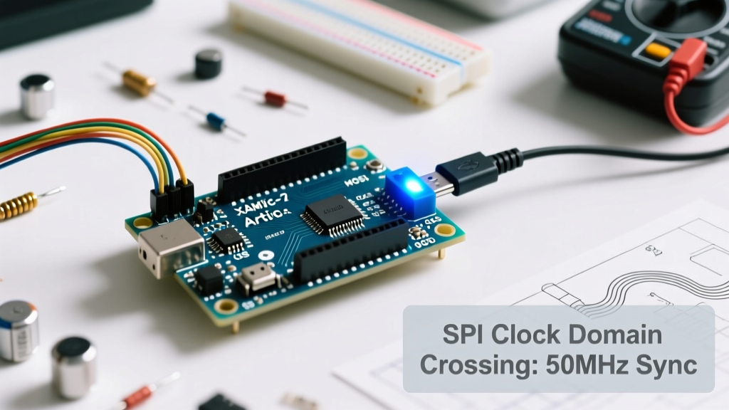
Writing the SPI slave logic in Verilog for the FPGA is where most tutorials fail to address real-world hardware physics. The SPI clock (SCK) generated by the Arduino is entirely asynchronous to the FPGA's internal system clock (e.g., a 48 MHz PLL generated by the iCE40's internal oscillator).
If you attempt to read the SPI data buffer directly using the FPGA's 48 MHz system clock, you will encounter metastability—a state where a flip-flop fails to resolve to a stable 1 or 0 within a single clock cycle, leading to catastrophic system crashes or silent data corruption.
Implementing a 2-FF Synchronizer and DCFIFO
To safely cross from the SPI clock domain to the internal FPGA clock domain, you must implement a Dual-Clock FIFO (DCFIFO) for the data payload, and a 2-Flip-Flop (2-FF) synchronizer for the Chip Select (CS) line.
// Verilog: 2-FF Synchronizer for Chip Select (CS)
module sync_2ff (
    input wire clk_sys,      // 48 MHz Internal FPGA Clock
    input wire rst,
    input wire cs_async,     // Asynchronous CS from Arduino SPI
    output reg cs_sync       // Synchronized CS for internal logic
);
    reg cs_meta;
    always @(posedge clk_sys or posedge rst) begin
        if (rst) begin
            cs_meta <= 1'b1;
            cs_sync <= 1'b1;
        end else begin
            cs_meta <= cs_async;
            cs_sync <= cs_meta;
        end
    end
endmodule
By passing the CS line through two consecutive flip-flops clocked by the 48 MHz system clock, you reduce the probability of metastability propagating into your state machine to less than one failure per million years of continuous operation (MTBF). The actual SPI data bits should be shifted into a small DCFIFO using the Arduino's SCK as the write clock, and read out by your DSP pipeline using the 48 MHz read clock.
Arduino SPI Master Implementation
On the Arduino side, we utilize the native hardware SPI peripheral of the SAMD21. Using the standard Arduino SPI Library, we configure the bus for SPI Mode 0 (CPOL=0, CPHA=0), which is the industry standard for most memory and peripheral chips.
#include <SPI.h>

const int csPin = 10;

void setup() {
  Serial.begin(115200);
  pinMode(csPin, OUTPUT);
  digitalWrite(csPin, HIGH); // Deselect FPGA

  // Initialize SPI bus but do not set global settings yet
  SPI.begin();
}

void loop() {
  // Transaction-based SPI ensures settings are correct for this specific device
  SPI.beginTransaction(SPISettings(8000000, MSBFIRST, SPI_MODE0));

  digitalWrite(csPin, LOW); // Assert Chip Select

  // Send a command byte (e.g., 0xAA to trigger FPGA DSP routine)
  SPI.transfer(0xAA);

  // Send a 16-bit payload
  SPI.transfer16(0x1F3E);

  digitalWrite(csPin, HIGH); // Deassert Chip Select
  SPI.endTransaction();

  delay(100); // Wait for FPGA to process
}
Notice the use of SPI.beginTransaction() and SPI.endTransaction(). This is critical in modern Arduino programming. It prevents conflicts if your sketch later incorporates a library for an SD card or a Wi-Fi module (like the Nano 33 IoT's NINA-W102) that might attempt to alter the SPI bus speed or clock polarity.
Advanced Troubleshooting and Edge Cases
Even with perfect code, physical layer issues can disrupt the Arduino and FPGA handshake. Use the following diagnostic matrix to resolve common integration failures.
| Symptom | Root Cause | Engineering Solution |
|---|---|---|
| FPGA receives random bytes when Arduino is idle. | Floating CS line picking up EMI during Arduino boot sequence. | Add a 10kΩ pull-up resistor on the CS line to 3.3V. Ensure Arduino initializes CS pin as HIGH before calling SPI.begin(). |
| Data is shifted by one bit (e.g., 0x80 becomes 0x40). | Incorrect SPI Mode (CPOL/CPHA mismatch). | Verify FPGA Verilog samples MISO on the rising edge and shifts MOSI on the falling edge for Mode 0. |
| Arduino resets randomly during heavy FPGA computation. | Ground bounce / Voltage droop due to shared power rail impedance. | Isolate power supplies. Use a star-ground topology. Add a 100µF bulk capacitor and a 0.1µF ceramic decoupling capacitor near the FPGA power pins. |
| Communication drops when connecting USB oscilloscope. | Ground loop introduced by the scope's earth-grounded probe. | Use differential probing or ensure the oscilloscope and the Arduino/FPGA share the same isolated AC mains circuit. |
Verifying Signal Integrity
If you have access to a digital storage oscilloscope (DSO) with at least 100 MHz bandwidth, probe the SCK line directly at the FPGA input pin (after the 33Ω resistor). You should see clean, crisp square waves. If the waveform resembles a "shark fin" (RC decay), your parasitic capacitance is too high—shorten your jumper wires or reduce the SPI clock speed to 4 MHz. If you see severe overshoot exceeding 3.6V, increase the series termination resistor to 47Ω or 68Ω to better match the characteristic impedance of your breadboard traces.
Conclusion
Successfully bridging an Arduino and FPGA via SPI transforms a simple microcontroller project into a high-performance, heterogeneous computing platform. By respecting the 3.3V logic boundaries, implementing proper clock domain crossing inside the FPGA fabric, and treating the physical wiring as a high-frequency transmission line rather than a simple DC connection, you guarantee robust, error-free data transfer. For further reading on FPGA I/O standards and SPI timing diagrams, consult the Lattice iCE40 Family Data Sheet and the Digilent FPGA Reference Manuals, which provide exhaustive details on bank voltage configurations and setup/hold time requirements.