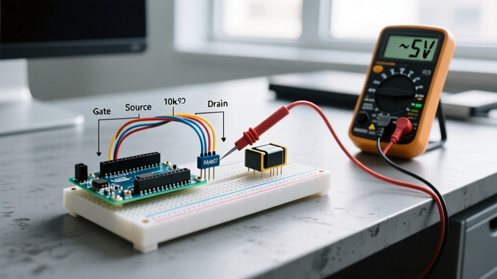

The Ultimate Arduino MOSFET Quick Reference
Microcontrollers like the ATmega328P (Arduino Uno/Nano) and ESP32 are incredibly versatile, but their GPIO pins are strictly limited to low-voltage, low-current outputs—typically 5V or 3.3V at a maximum of 20mA to 40mA. To control high-power loads like 12V LED strips, DC motors, solenoids, or heating elements, you must use a transistor. While BJTs were common in the past, the Arduino MOSFET (Metal-Oxide-Semiconductor Field-Effect Transistor) is the modern standard due to its voltage-driven gate, near-infinite input impedance, and high current-handling capabilities.
This quick-reference guide cuts through the fluff and provides actionable, expert-level answers to the most common MOSFET selection, wiring, and troubleshooting questions encountered by makers and embedded engineers in 2026.
Logic-Level N-Channel MOSFET Comparison Matrix
Not all MOSFETs are created equal. Below is a curated list of N-channel MOSFETs optimized for microcontroller logic levels, complete with real-world 2026 pricing and critical datasheet specifications.
| Model | Package | Max V_DS | R_DS(on) @ V_GS = 4.5V | Max I_D | Est. Price (2026) |
|---|---|---|---|---|---|
| IRLB8721PbF | TO-220 | 30V | 6.2 mΩ | 62A | $1.80 |
| IRLZ44N | TO-220 | 55V | 22.0 mΩ | 47A | $1.20 |
| AO3400A | SOT-23 | 30V | 40.0 mΩ | 5.7A | $0.15 |
| CSD17313Q2 | SON 3x3 | 30V | 3.4 mΩ | 25A | $0.65 |
Note: Always verify the R_DS(on) at your specific microcontroller's logic voltage (e.g., 3.3V or 5V), not just the absolute maximum ratings.
Frequently Asked Questions & Troubleshooting
1. Why won't my IRF520 or IRFZ44N turn on fully with a 5V Arduino?
This is the most common beginner mistake in power electronics. Makers often look at the V_GS(th) (Gate-Source Threshold Voltage) on a datasheet, see that it is rated at 2.0V to 4.0V, and assume a 5V Arduino pin will fully turn on an IRF520.
The Reality: V_GS(th) is merely the voltage at which the MOSFET begins to conduct a tiny leakage current (usually 250µA). To achieve the low R_DS(on) (on-state resistance) required to pass high current without overheating, you must look at the V_GS specified in the R_DS(on) test conditions. Standard-level MOSFETs like the IRF520 require V_GS = 10V for full enhancement. When driven by a 5V Arduino, the IRF520 operates in the linear (ohmic) region, acting as a high-value resistor. It will generate massive amounts of heat and likely fail catastrophically.
Expert Rule: Always select a 'Logic-Level' MOSFET (often denoted by an 'L' in the prefix, like IRLB or IRLZ) and verify the datasheet guarantees low R_DS(on) at V_GS = 4.5V (for 5V logic) or V_GS = 2.5V (for 3.3V logic). For a deep dive on reading these specifications, refer to the DigiKey TechZone guide on MOSFET specifications.
2. Do I need a gate series resistor and a pull-down resistor?
Yes, both are critical for reliability and microcontroller protection, though for different reasons.
- Gate Series Resistor (R_G): A MOSFET gate acts like a small capacitor (C_iss). When the Arduino pin goes HIGH, it dumps current into this capacitor. The ATmega328P has an absolute maximum rating of 40mA per pin. Without a resistor, the instantaneous inrush current can exceed this limit, degrading the microcontroller's silicon over time. A 220Ω resistor limits the peak current to roughly 22mA (5V / 220Ω), keeping the GPIO pin safe while still allowing fast enough switching for standard PWM frequencies (up to 20kHz).
- Gate Pull-Down Resistor (R_PD): When an Arduino powers up or resets, its GPIO pins are in a high-impedance (floating) state before the
pinMode()function executes. During this window, electromagnetic noise or capacitive coupling can induce a voltage on the floating gate, partially turning on the MOSFET. This can destroy your load or the MOSFET itself. A 10kΩ to 100kΩ resistor wired between the Gate and Source ensures the gate is actively pulled to 0V (OFF) whenever the microcontroller pin is floating.
3. Why does my MOSFET explode when switching a motor or relay?
If you are switching an inductive load (motors, solenoids, relays, fans), you are dealing with inductive kickback. Inductors resist changes in current. When the MOSFET turns off, the collapsing magnetic field in the load generates a massive reverse voltage spike (V = -L * di/dt). This spike routinely exceeds 100V, instantly breaching the MOSFET's V_DSS (Drain-Source Breakdown Voltage) and causing an avalanche failure, which usually results in a short circuit and a shattered package.
The Fix: You must install a flyback diode in reverse parallel across the load (cathode to positive, anode to the MOSFET drain).
- For Relays/Solenoids (Low Frequency): A standard 1N4007 rectifier diode is sufficient and costs pennies.
- For DC Motors (High-Frequency PWM): Standard diodes have a slow reverse recovery time (t_rr), which causes them to conduct backwards during high-speed PWM switching, leading to overheating. Use a Schottky diode like the SS34 or 1N5819, which has a near-zero recovery time. See All About Circuits for foundational semiconductor behavior regarding inductive transients.
4. Will 5V logic-level MOSFETs work with 3.3V boards like the ESP32 or RP2040?
Not reliably. The term 'Logic-Level' was coined in the 1990s when 5V TTL was the standard. Many older logic-level MOSFETs (like the IRLZ44N) have an R_DS(on) curve that drops off sharply below 4.0V. If you drive an IRLZ44N with a 3.3V ESP32 GPIO, it will not fully enhance, leading to high resistance and severe thermal throttling.
For 3.3V microcontrollers, you must select MOSFETs specifically binned for V_GS = 2.5V or 1.8V. Excellent modern choices include the CSD17313Q2 (Texas Instruments) or the ubiquitous AO3400A for lower-current applications (<5A). You can explore modern low-voltage gate drive requirements via the Texas Instruments MOSFET portal.
Thermal Management & PCB Layout Rules
Even a 'low resistance' MOSFET generates heat. To calculate the temperature rise of your MOSFET, use the Junction-to-Ambient thermal resistance (R_θJA) provided in the datasheet.
Example Calculation: You are using a bare IRLB8721PbF (TO-220 package) to switch 15A at 12V. The R_DS(on) at 5V is roughly 8mΩ (0.008Ω).
- Power Dissipation (P): I² * R = 15² * 0.008 = 1.8 Watts.
- Thermal Rise: A bare TO-220 has an R_θJA of ~62°C/W. Temperature rise = 1.8W * 62°C/W = 111.6°C above ambient.
- Result: If your room is 25°C, the MOSFET junction will hit 136.6°C, dangerously close to the 175°C silicon limit, and the case will be hot enough to melt PLA 3D-printed enclosures.
Actionable Advice: If your calculated power dissipation exceeds 1W, you must either attach a clip-on heatsink to the TO-220 package, increase the copper pour area on your custom PCB to act as a planar heatsink (for SMD packages like SON or DPAK), or select a MOSFET with a lower R_DS(on). Always measure the actual case temperature with a thermocouple during a 30-minute burn-in test to validate your thermal design.