
The Anatomy of an Arduino to LED Strip Failure
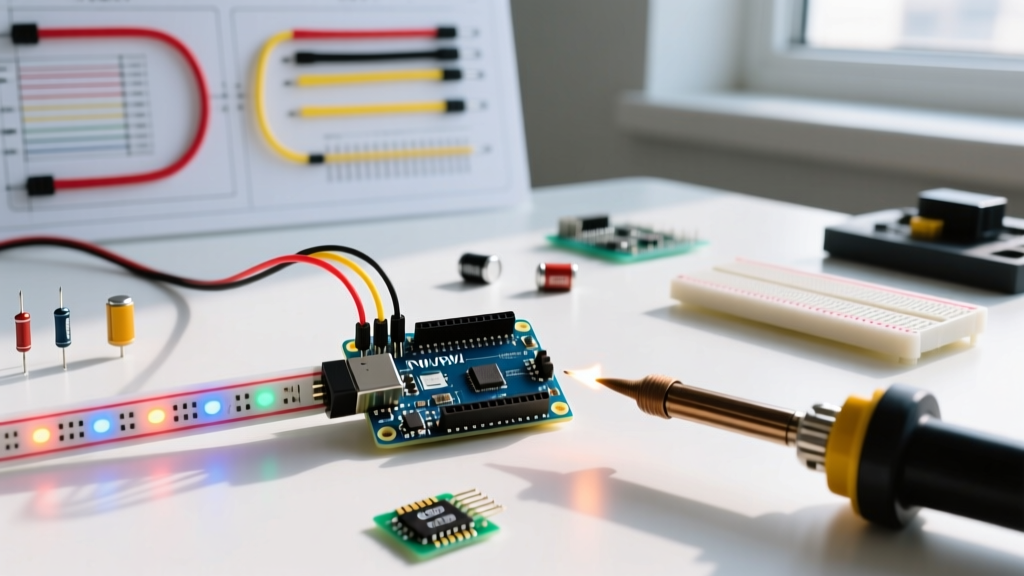
Connecting a microcontroller to addressable LEDs is a rite of passage for electronics makers, but the pipeline from an Arduino to LED strip hardware is fraught with subtle electrical and software edge cases. Whether you are building an ambient TV backlight or a large-scale interactive art installation, encountering flickering pixels, random color bursts, or complete data blackouts is incredibly common. In 2026, the market is flooded with high-density 240 LEDs/meter strips and ultra-miniature WS2812C-2020 chips that demand stricter signal integrity than their older counterparts.
This comprehensive diagnostic guide bypasses generic advice and dives deep into the exact failure modes, electrical measurements, and hardware fixes required to stabilize your Arduino to LED strip connection. We will cover logic level degradation, voltage drop calculations, inrush current brownouts, and library timing mismatches.
1. The Logic Level Mismatch (The #1 Data Killer)
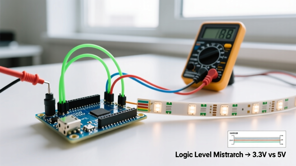
The most frequent cause of erratic LED behavior is a logic level voltage mismatch between the microcontroller and the addressable strip. The ubiquitous WS2812B LED operates on a 5V power supply and requires a minimum High-Level Input Voltage ($V_{IH}$) of roughly 0.7 × VDD, which translates to 3.5V to reliably register a logic '1'.
The 3.3V Microcontroller Trap
If you are using a modern 3.3V board like the ESP32-S3, ESP8266, or Arduino Nano 33 IoT, your data pin outputs a maximum of 3.3V. Because 3.3V is below the 3.5V threshold, the first LED in the chain might barely interpret the signal, acting as a flawed, degraded level shifter for the second LED. This results in the classic symptom: the first pixel lights up correctly, but the rest of the strip flickers green, magenta, or remains dead.
The Fix: Do not rely on the first LED to shift your voltage. You must use a dedicated logic level shifter. The gold standard for 800kHz PWM data lines is the SN74AHCT125 IC. Unlike slow optocouplers or MOSFET-based bi-directional shifters that introduce destructive propagation delays, the AHCT125 accepts 3.3V logic on its input and cleanly outputs 5V logic powered by the LED strip's 5V rail. A breakout board for the SN74AHCT125 typically costs between $3 and $5 in 2026 and is mandatory for any 3.3V Arduino to LED strip project. For a deeper understanding of digital logic thresholds, refer to the SparkFun Logic Levels Tutorial.
2. Voltage Drop and Power Injection Failures
Addressable LEDs are power-hungry. A standard 5-meter strip with 60 LEDs per meter contains 300 pixels. At maximum brightness (full white), each pixel draws approximately 60mA. This means a single 5-meter strip can pull up to 18 Amps at 5V. Powering this from a standard 5V 2A USB adapter will instantly cause severe voltage drops and brownouts.
Calculating Wire Gauge and Injection Points
Even if you have a massive 5V 20A power supply, pushing 18A through the strip's internal 22AWG copper traces will result in a massive voltage drop. Copper wire has a resistance of roughly 16.14 ohms per 1000 feet for 22AWG. By the time power reaches the 3rd meter of the strip, the voltage may have dropped below 4.3V. When WS2812B chips receive less than 4.5V, their internal regulators fail to maintain the data signal, causing the far end of the strip to glow dimly, turn pink/red, or shut off entirely.
Expert Rule of Thumb: Never rely on the strip's end-to-end power traces for runs longer than 2 meters. You must inject both 5V and Ground from your power supply into the strip every 1.5 to 2 meters using 18AWG or 16AWG silicone wire.
For high-density 144 LEDs/m or 240 LEDs/m strips (which cost roughly $25 to $45 per 5-meter reel in 2026), power injection every 1 meter is strictly required. Always measure the voltage at the furthest injection point with a multimeter while the strip is displaying full white to ensure it remains above 4.7V.
3. Common Ground and Inrush Current Brownouts
The Floating Ground Error
Data signals are not absolute; they are relative to the ground plane. If your Arduino and your LED power supply do not share a common ground, the data line is floating. The LEDs will interpret electrical noise as data, resulting in random, seizure-inducing color flashes. Always run a dedicated ground wire from the Arduino's GND pin to the LED power supply's negative terminal.
Inrush Current and Arduino Resets
When a large LED strip transitions from black to full white, it draws maximum current almost instantaneously. This massive inrush current can pull the shared 5V rail down for a few milliseconds. If your Arduino is powered from the same 5V rail (or if the ground bounce is severe enough), the microcontroller will brownout and reset. To prevent this, place a large 1000µF to 2200µF electrolytic capacitor (rated for at least 6.3V or 10V) directly across the VCC and GND terminals at the start of the LED strip. This capacitor acts as a local energy buffer, absorbing the inrush spike and protecting your microcontroller.
Diagnostic Matrix: Symptoms vs. Root Causes
Use this structured matrix to quickly identify the root cause of your Arduino to LED strip connection errors based on visual symptoms.
| Visual Symptom | Probable Root Cause | Hardware / Code Fix |
|---|---|---|
| First pixel works, rest flicker random colors | 3.3V logic failing to meet 5V $V_{IH}$ threshold | Install SN74AHCT125 level shifter on data line |
| Strip turns pink/red at the far end | Severe voltage drop across thin PCB traces | Inject 5V and GND every 1.5 meters with 18AWG wire |
| Arduino resets when strip turns bright white | Inrush current causing 5V rail brownout | Add 1000µF capacitor across LED strip VCC/GND |
| Entire strip shows chaotic, seizure-like flashing | Missing common ground between MCU and PSU | Connect Arduino GND to LED PSU negative terminal |
| Colors are swapped (e.g., Red shows as Green) | Library color order mismatch (RGB vs GRB) | Change FastLED color order to GRB or RGB |
Software & Library Edge Cases in 2026
Hardware is only half the battle. The software libraries driving the LEDs must precisely match the timing requirements of the silicon. The Adafruit NeoPixel Überguide remains a foundational resource, but modern development often relies on the FastLED library for advanced color math and multi-strip management.
Color Order and Timing Mismatches
Not all WS2812 chips are wired identically internally. While most standard strips use a GRB (Green-Red-Blue) color order, many newer SK6812 strips and specific batches of WS2812B use RGB. If your code commands red, but the LEDs turn green, you have a color order mismatch. In FastLED, this is fixed in the initialization macro:
FastLED.addLeds<WS2812B, DATA_PIN, GRB>(leds, NUM_LEDS);
Furthermore, consult the FastLED Chipset Reference if you are using SPI-based APA102 (DotStar) strips. APA102 strips require both a Data and a Clock pin. A common error is wiring the Clock line to a pin that does not support hardware SPI on your specific Arduino board, forcing the library into slow software-emulated SPI, which causes visible flickering at high refresh rates.
Essential Protection Components: Myth vs. Reality
You will often see older tutorials demanding a 470Ω resistor on the data line. Here is the 2026 reality of protection components:
- The 470Ω Data Resistor: This resistor is placed between the Arduino data pin and the LED strip's DIN pad. Its primary purpose is to protect the microcontroller's GPIO pin from catastrophic damage if you accidentally wire the 5V power to the data line. It also slightly smooths out high-frequency ringing on long data wires. Keep it in your design, placed as close to the LED strip's DIN as possible.
- The 1000µF Buffer Capacitor: As mentioned, this is non-negotiable for strips exceeding 100 pixels to prevent ground bounce and inrush resets. Ensure correct polarity; reversing an electrolytic capacitor will cause it to vent or explode.
- Fuses and Relays: For permanent installations drawing over 10A, integrate an inline automotive blade fuse (e.g., 15A) on the main 5V positive line from the power supply to prevent wire melting in the event of a dead short.
By systematically verifying your logic levels, calculating your power injection points, and ensuring robust grounding, you can eliminate 99% of all Arduino to LED strip connection errors and build rock-solid, professional-grade lighting systems.