
The Anatomy of Serial Communication in Arduino
When makers first blink an LED, the immediate next step is usually printing 'Hello World' to the Serial Monitor. Yet, the underlying mechanics of serial communication in Arduino environments are often treated as a black box. Understanding what happens between your C++ sketch and the physical copper traces is critical for debugging complex sensor networks, preventing data loss, and integrating mixed-voltage systems.
At its core, standard Arduino serial communication relies on UART (Universal Asynchronous Receiver-Transmitter). Unlike SPI or I2C, UART is asynchronous—meaning it does not use a dedicated clock line to synchronize data transfers. Instead, both the sender and receiver must agree on a timing parameter known as the baud rate before transmission begins.
Expert Insight: Because UART lacks a clock signal, it is highly susceptible to timing drift. If the transmitter and receiver clocks drift apart by more than 2-3% over the duration of a 10-bit data frame, the receiver will sample the wrong bit, resulting in corrupted data or 'garbage' characters in your Serial Monitor.
Hardware Layer: USART and the USB Bridge
On a classic Arduino Uno R3, serial communication is handled by the USART peripheral built into the ATmega328P microcontroller. The ATmega328P operates at 5V logic levels and outputs serial data on physical pins D0 (RX) and D1 (TX).
However, modern computers do not have native RS-232 or 5V TTL UART ports; they use USB. To bridge this gap, the Uno R3 includes a secondary microcontroller, typically the ATmega16U2. This chip acts as a USB-to-Serial converter. When you call Serial.println() in your sketch, the ATmega328P sends TTL-level UART signals to the ATmega16U2, which packages the data into USB CDC (Communication Device Class) packets and sends it to your PC.
Multi-UART Architectures
If you are building a project that requires talking to a GPS module, a cellular modem, and the PC simultaneously, a standard Uno will bottleneck. You must step up to boards with multiple hardware UARTs:
- Arduino Mega 2560: Features 4 hardware UARTs (Serial, Serial1, Serial2, Serial3).
- ESP32-WROOM-32: Features 3 hardware UARTs. Note that UART0 is typically reserved for USB/Flash communication, leaving UART1 and UART2 for peripheral mapping via the GPIO matrix.
Baud Rate Mathematics and Clock Drift
The baud rate defines the number of signal transitions (bits) per second. A standard 9600 baud rate means 9,600 bits are transmitted per second. The Arduino IDE calculates the hardware register value (UBRR - USART Baud Rate Register) using the microcontroller's clock speed (F_CPU) and the desired baud rate.
The formula for the standard asynchronous mode is:
UBRR = (F_CPU / (16 * Baud)) - 1
Because the UBRR must be an integer, rounding errors occur. This introduces a timing error percentage. If the error exceeds roughly ±2.5%, reliable communication degrades. Below is a breakdown of actual error rates on a standard 16 MHz Arduino Uno.
| Target Baud Rate | Calculated UBRR | Actual Baud Rate | Error % | Reliability Verdict |
|---|---|---|---|---|
| 9600 | 103 | 9615 | +0.16% | Excellent |
| 57600 | 16 | 58823 | +2.12% | Acceptable |
| 115200 | 8 | 111111 | -3.55% | Risky (May fail over long cables) |
| 250000 | 3 | 250000 | 0.00% | Perfect (But requires custom receiver) |
| 500000 | 1 | 500000 | 0.00% | Perfect |
Notice that 115200 baud—the most common high-speed default—actually carries a -3.55% error on a 16 MHz AVR chip. While usually fine for short jumper wires, this error margin can cause frame errors when using long RS-485 cables or communicating with strict external peripherals. According to SparkFun's UART guidelines, keeping the total system error (transmitter + receiver) under 5% is mandatory for stable links.
The 64-Byte Ring Buffer: Where Data Goes to Die
One of the most misunderstood aspects of serial communication in Arduino is the receive buffer. When a byte arrives at the RX pin, the USART hardware triggers an interrupt. The Interrupt Service Routine (ISR) grabs that byte and places it into a software ring buffer managed by the HardwareSerial class.
On standard AVR boards (Uno, Nano), this buffer is exactly 64 bytes. On the Mega2560, it is 256 bytes. When you call Serial.read(), you are not reading directly from the hardware pin; you are popping the oldest byte out of this RAM buffer.
The Overrun Failure Mode
If your main loop() is bogged down by blocking code—such as delay(), long analogRead() averaging, or blocking network requests—the buffer will fill up. Once byte 65 arrives, the buffer overflows. The USART hardware will set an Overrun Error (OR) flag, and the incoming byte is permanently discarded.
Actionable Fix: Never use delay() in production serial code. Implement non-blocking timing using millis() and parse serial data using a state machine or a library like Serial.readBytesUntil() with strict timeout parameters.
The Truth About Serial.flush()
Prior to Arduino IDE 1.0, Serial.flush() cleared the receive buffer. Today, it does the exact opposite: it blocks program execution until all outgoing bytes in the transmit buffer have been physically shifted out of the TX pin. Using Serial.flush() unnecessarily will stall your microcontroller and cause missed sensor readings.
Logic Level Translation: 5V vs 3.3V
A critical hardware trap in modern maker projects involves mixing 5V AVRs with 3.3V microcontrollers (like the ESP32, Raspberry Pi Pico, or SAMD21). The GPIO pins on 3.3V chips typically have an absolute maximum voltage rating of 3.6V. Feeding a 5V TX signal from an Arduino Uno directly into a 3.3V ESP32 RX pin will degrade the silicon over time, eventually destroying the ESP32's UART peripheral.
To safely bridge these domains, you must use a logic level shifter. While resistor voltage dividers work for low-speed I2C, they distort the sharp square waves required for high-baud-rate UART.
- Best Practice: Use a bi-directional MOSFET-based level shifter (like the BSS138 breakout boards, costing roughly $2 to $4) or a dedicated IC like the CD4050 non-inverting buffer.
- Alternative: If communicating one-way from 5V to 3.3V, a simple diode (like a 1N4148) combined with a pull-up resistor to 3.3V on the RX line can safely clamp the voltage, though this is considered a 'hack' for rapid prototyping only.
Comparison Matrix: UART vs I2C vs SPI
While UART is foundational, understanding when to abandon it for a synchronous protocol is a hallmark of advanced embedded design.
| Feature | UART (Serial) | I2C (Wire) | SPI |
|---|---|---|---|
| Wires Required | 2 (TX, RX) + GND | 2 (SDA, SCL) + GND | 4 (MOSI, MISO, SCK, CS) + GND |
| Synchronization | Asynchronous | Synchronous | Synchronous |
| Topology | Point-to-Point | Multi-Master/Slave Bus | Single Master / Multi-Slave |
| Max Speed (Typical) | ~1 Mbps | 3.4 Mbps (HS-I2C) | 10+ Mbps |
| Best Use Case | Debugging, GPS, Cellular Modems | Sensors, OLEDs, EEPROM | High-res ADCs, SD Cards, TFT Displays |
Real-World Troubleshooting Checklist
When your serial output yields gibberish or fails entirely, run through this diagnostic sequence:
- Verify Common Ground: UART is single-ended, meaning the voltage is measured relative to ground. If the Arduino and the peripheral do not share a common GND connection, the voltage reference floats, resulting in random noise triggering false start bits.
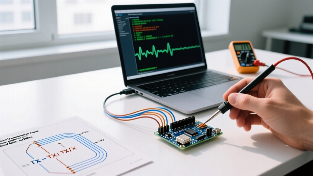
- Check TX/RX Crossover: The TX pin of Device A must connect to the RX pin of Device B. A common mistake is wiring TX-to-TX and RX-to-RX.
- Inspect Cable Capacitance: Standard jumper wires act as antennas and capacitors. If running UART over distances greater than 2 meters, the signal edges will degrade. Transition to RS-485 using differential transceivers (like the MAX485) for industrial or long-range environments.
- Confirm Baud Rate Matching: Ensure the peripheral isn't defaulting to an oddball baud rate (e.g., some older GPS modules default to 4800 or 38400, not 9600).
For deeper architectural details regarding the AVR USART registers, consult the official Microchip ATmega328P datasheet, specifically the section on 'USART0' framing and parity bit configuration. Mastering these hardware-level details transforms you from a script-kiddie copying serial snippets into a capable embedded systems engineer capable of designing robust, noise-immune communication networks.