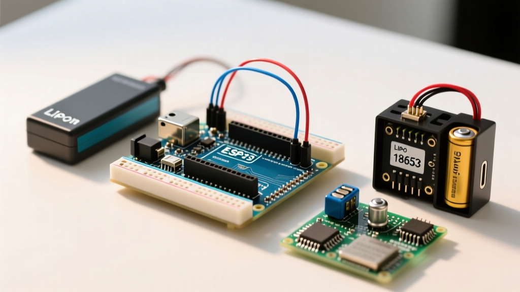

The Migration Mindset: Moving Beyond Tethered Power
Transitioning a microcontroller project from a tethered USB connection or a wall-wart adapter to an autonomous, off-grid setup is a major milestone in any maker's journey. However, when you first attempt to power Arduino with battery systems, the results are often disappointing. Projects that run flawlessly on a desk suddenly brown out when a servo motor engages, or they drain a 9V alkaline battery in less than 12 hours. This migration guide is designed to help you upgrade from legacy, inefficient power architectures to modern, high-efficiency Lithium-based systems, complete with Battery Management Systems (BMS) and firmware-level sleep optimizations.
The Case Against Legacy Battery Packs
Before upgrading, it is critical to understand why traditional battery packs fail in modern MCU applications. The standard 9V PP3 alkaline battery is arguably the worst power source for an Arduino Uno. Despite its high nominal voltage, a 9V battery typically offers a mere 400mAh to 550mAh capacity and suffers from high Equivalent Series Resistance (ESR). When your circuit demands a sudden current spike—such as activating an HC-SR04 ultrasonic sensor or a micro-servo—the voltage sags below the ATmega328P's brown-out detection threshold, causing a reset.
Similarly, 4x AA NiMH rechargeable packs (nominal 4.8V) struggle to maintain the 5V rail required by the Arduino's USB/5V pins, especially as the cells discharge and drop to 1.0V per cell. To achieve true autonomy, you must migrate to chemistries with low internal resistance and high energy density.
Battery Chemistry Matrix: Choosing Your Upgrade Path
Selecting the right cell chemistry is the foundation of your power upgrade. Below is a comparison matrix of the three most viable options for MCU projects in 2026.
| Chemistry | Nominal Voltage | Typical Capacity | Avg. Cost (2026) | Best Use Case |
|---|---|---|---|---|
| LiPo (Pouch) | 3.7V | 100mAh - 5000mAh | $3.00 - $18.00 | Compact, lightweight wearables and drones. |
| 18650 Li-ion | 3.6V / 3.7V | 2500mAh - 3500mAh | $4.50 - $8.00 | Long-term environmental sensors, robotics, high-drain. |
| LiFePO4 | 3.2V | 1500mAh - 3000mAh | $6.00 - $12.00 | Extreme temperature environments, 10+ year lifecycle solar nodes. |
For the vast majority of general-purpose upgrades, the 18650 Li-ion cell (such as the Samsung 35E or Panasonic NCR18650B) offers the best balance of cost, capacity, and physical robustness. According to comprehensive guides by Adafruit on Lithium-Ion and LiPoly batteries, these cells can safely deliver continuous currents of 5A to 10A, completely eliminating the voltage sag issues inherent to alkaline cells.
Hardware Migration: Bypassing the Linear Regulator
The most common mistake when attempting to power Arduino with battery setups is plugging a 7V-9V battery pack directly into the VIN pin or the barrel jack. The onboard AMS1117-5.0 linear regulator must drop the excess voltage as heat. If you supply 9V to the 5V rail, the regulator's efficiency is roughly 55% (5V / 9V). You are literally burning 45% of your battery capacity as thermal waste.
The Buck/Boost Upgrade
To achieve 90%+ efficiency, you must bypass the onboard linear regulator entirely and use a switching regulator. For a 3.7V Li-ion or LiPo cell, you need a Boost Converter to step the voltage up to 5V. For a 2S (7.4V) Li-ion pack, you need a Buck Converter.
- Pololu S7V8A (Step-Up/Step-Down): Priced around $8.95, this module accepts 2.7V to 11.8V and outputs a highly stable 5V at up to 1.5A. It is ideal for single-cell 18650 setups where the voltage drops from 4.2V down to 3.0V.
- Texas Instruments TPS63020 Breakouts: Available for roughly $4.00 on third-party marketplaces, this IC offers exceptional efficiency (up to 96%) and a quiescent current draw of less than 30µA, making it perfect for deep-sleep applications.
Wiring Warning: Never connect the 5V output of your switching regulator to the Arduino's 5V pin while the USB cable is simultaneously plugged in. This back-powers the USB port and can destroy your computer's USB controller or the Arduino's ATmega16U2 chip. Use a Schottky diode (like the 1N5817) or an ideal diode controller IC (like the LTC4412) if automatic USB/Battery switching is required.
Step-by-Step 18650 + BMS Architecture
Migrating to raw Lithium cells requires a Battery Management System to prevent over-discharge, which permanently damages the cell's chemistry, and overcharge, which poses a severe fire risk.
- Select the BMS: The TP4056 charging module with integrated DW01A protection and 8205A dual MOSFET is the industry standard for single-cell DIY projects. It costs under $1.50 and handles 1A linear charging via USB-C or Micro-USB.
- Wire the Cell: Connect the 18650 positive and negative terminals to the BMS pads labeled
B+andB-. - Wire the Load: Connect your boost converter's input to the BMS pads labeled
P+andP-. The DW01A chip will physically disconnect theP-line if the cell voltage drops below 2.4V, saving the battery from fatal deep-discharge. - Regulate and Deliver: The boost converter steps the 3.0V-4.2V from the BMS up to a clean 5V, which is then wired directly to the Arduino's
5Vpin, completely bypassing the inefficient onboard regulator.
Adding Solar Autonomy (MPPT Integration)
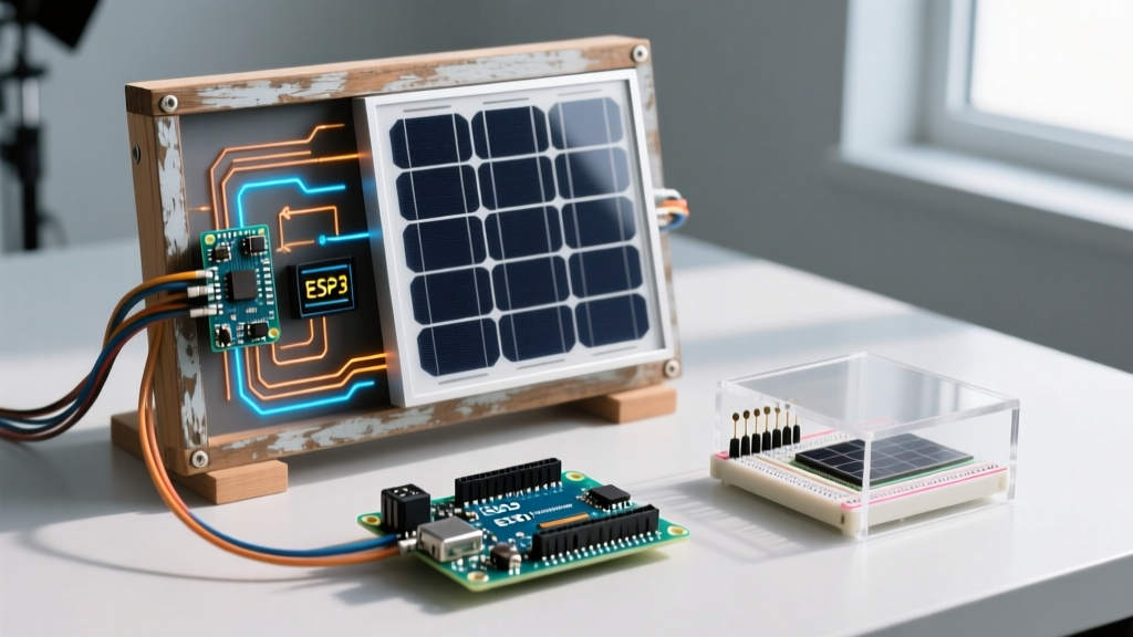
If your migration goal is a permanent outdoor installation, you must integrate a solar charge controller. Do not connect a 6V solar panel directly to a TP4056; the TP4056 is a linear charger and will overheat if the input voltage is too high. Instead, upgrade to a CN3791 MPPT (Maximum Power Point Tracking) charge controller module (approx. $2.50). The CN3791 dynamically matches the solar panel's impedance to extract maximum wattage, charging your 18650 cell efficiently even under partial cloud cover.
Firmware Migration: From Milliamps to Microamps
Hardware efficiency only solves half the equation. A standard Arduino Uno drawing 45mA continuously will drain a 3000mAh 18650 cell in roughly 66 hours. To achieve months of battery life, you must migrate your firmware to utilize hardware sleep modes.
AVR Sleep Modes (ATmega328P)
Using the official Arduino Low Power documentation as a baseline, you should migrate your code to use the avr/sleep.h library. The POWER_DOWN mode shuts off the CPU, ADC, and timers, reducing current draw to approximately 35µA when paired with a Watchdog Timer (WDT) interrupt.
#include <avr/sleep.h>
#include <avr/wdt.h>

void enterSleep(void) {
  ADCSRA = 0; // Disable ADC to save ~250µA
  set_sleep_mode(SLEEP_MODE_PWR_DOWN);
  sleep_enable();
  sleep_mode(); // CPU halts here until WDT interrupt
  sleep_disable();
}
Pro-Tip: If you are designing a custom PCB around the ATmega328P, disable the Brown-Out Detector (BOD) via the extended fuse bits. The BOD constantly monitors voltage and draws an additional 18µA to 45µA, which is unacceptable for ultra-low-power battery nodes.
ESP32 Deep Sleep Migration
If you are upgrading from an 8-bit AVR to an ESP32 for Wi-Fi capabilities, battery management becomes even more critical due to the ESP32's high active current spikes (up to 240mA during RF transmission). According to the Espressif ESP-IDF Sleep Modes API, you must utilize esp_deep_sleep_start(). In deep sleep, the ESP32 shuts down the CPU and most peripherals, leaving only the RTC controller and ULP (Ultra-Low-Power) coprocessor active, drawing a mere 5µA to 10µA.
Critical Failure Modes to Avoid
As you finalize your migration to battery power, audit your design against these common edge cases:
- Cold Weather Voltage Sag: Li-ion chemistry slows down significantly below 0°C (32°F). A cell that reads 3.8V at room temperature may sag to 2.9V under a 500mA load in freezing temperatures, triggering the BMS low-voltage cutoff. If deploying outdoors in winter, migrate to LiFePO4 chemistry or use a resistive heating pad controlled by a thermistor.
- Quiescent Current Leaks: Many cheap boost converters advertise high efficiency but have a quiescent current (Iq) of 5mA to 15mA. This phantom drain will kill your battery in a few weeks even if the Arduino is in deep sleep. Always verify the Iq on the module's datasheet before purchasing.
- USB Backpowering via I/O Pins: If your Arduino is powered down to save battery, but a connected sensor (like an SD card module) is still receiving 3.3V from a separate source, current can flow backward through the Arduino's I/O protection diodes, causing erratic behavior and battery drain. Use MOSFET load switches (like the TI TPS2553) to physically cut power to peripheral sensors during sleep cycles.
Conclusion
Learning how to properly power Arduino with battery systems requires abandoning the convenience of linear regulators and alkaline cells. By migrating to an 18650 Li-ion architecture, integrating a dedicated BMS, utilizing high-efficiency buck/boost converters, and aggressively managing firmware sleep states, you can transform a desk-bound prototype into a rugged, autonomous sensor node capable of running for months or even years on a single charge.